| Synertek SYM-1 Remote Network Reset February 2011 |
||||||||||||||||||||||||||||||||||||
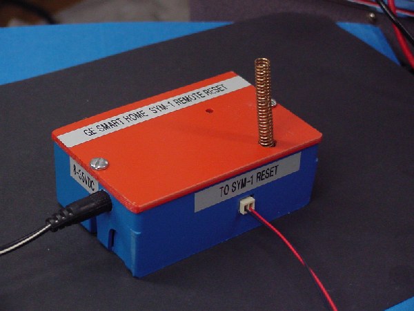 Recent interest in rebuilding the old SYM-1 computer resulted in having complete access to it via the internet or my home network. I ended that dissertation with the requirement to reset the SYM-1 via remote means as well. This page is the final result of those efforts. The picture above is my little remote reset box. My SYM-1 Remote Reset is based upon the GE Smart Home Indoor Outlet Adapter model RF100RXPS. In a earlier document I talk about the conversion of my GE Smart Remote control model RF2000KINPS and its ability to allow full control via the internet. That conversion allow me to turn on eight different zones (or channels) in my home of AC operated appliances, lights or whatever. The GE Smart Home system is really neat as it performs all it communication via a 320MHz UHF communications link. Thus, no cables or coupling of control to the AC power lines are needed. Each little receiving adapter gets their control over this UHF link signal. A second article covers converting the GE Outlet Adapter, a receiver, to perform as a generic relay control output rather than a controlled AC outlet. This document describes the construction of a remote reset box for my SYM-1 via a conversion of the RF100RXPS adapter. I discard the original cabinet and use only the internal printed circuit board (PCB). The result is a remote controlled circuit that will present a short duration reset on the SYM-1 computer. So if I'm using my SYM-1 from a remote location and it hangs I will be able to reset it and continue with my computing. Please review the prior articles if you want to duplicate my efforts or want to do something similar. In the GE Outlet Adapter article I describe
the
schematic of the original RF100RXPS adapter. This conversion
first
involves removing all the AC input and output wiring from the
PCB. Thankfully the PCB has labels for all parts. Here is a
list of what gets removed.
Schematic
of
SYM-1
Reset
Remote
Once all the above components are removed
you will now install the new components to the board. I used
existing traces and lands to mount some of the new components and added
extra holes to the PCB to mount additional. I'm not going to
provide a detailed component location description as I just mounted
them where ever they fit as I went along. An experienced
experimenter should have no problem. You will just need to pay
attention to where the traces go on the underside of the PCB to make
sure your placement agrees with the new schematic diagram that follows.
The new schematic for the modified RF100RXPS PCB is shown below. Notice component ID's that have a "*" in front of them are newly added parts. The new circuit does runs entirely off low DC voltage now. If your like me you have a plenitude of wall DC power supplies that have collected over the years. I must have 40 or 50 of these wall warts that have come from long lost or thrown out electronic gadgets over the past ten years. For those unfamiliar with the term "wall wart" it is electronic slang for a small transformer and/or DC power supply with a plug attached, that hangs off of your electrical outlet. Cell phones, portable CD players, digital cameras all use them and so do hundreds of other items around your home. Well my little SYM-1 Remote Reset box also uses one. The wall wart you'll need is one that can provide 8-35 VDC at around 100mA. I am actually using a 6VDC 400mA unit. At the current draw of this circuit it actually puts out around 14VDC. Those little DC wall warts usually are not a regulated DC output so if it has a higher current rating than 100mA it probably will put out a much higher DC voltage than what is stated on the label. I recommend an DC wall wart and not one that puts out AC voltage! Let's have a look at the schematic.  You
can
click
on
the above schematic to view a larger version or click here to view and print a pdf version.
I would recommend printing out
the pdf version of the original
RF100RXPS schematic to compare them side-by-side as I describe the
changes. After removal
of all the components that will not be used by the SYM-1 Remote Reset
we
will then begin adding the new parts to our PCB. There are
four main areas that get added. First are the power supply
parts. These consists of *J10, *U11, *E1, and *E2.
*J10 is a DC Power Port jack that is chosen to match the plug on your
wall wart. *U11 is a small 5V three-pin regulator(LM78L05) that
provides +5VDC for our entire circuit. All these components can
be
viewed from the top of the PCB as shown below.
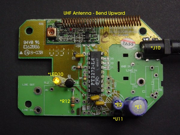 Top View of SYM-1 Remote Reset PCB
On the above picture we also have a few other new components. Since we removed the old relay and sub-PCB mounted LED those get replaced with a new LED *LED10 and the old relay coil is replaced by resistor *R12. The resistor gets soldered directly where the old relay coil contacts were soldered in. The new LED is soldered into the holes where the old LED wires attached to. The new LED is a visual indicator that still lights when our GE Smart Home controller activates this receiver adapter. Any style of leaded LED can be used and the color is up to your discretion. Now lets move on to the bottom side PCB circuitry. 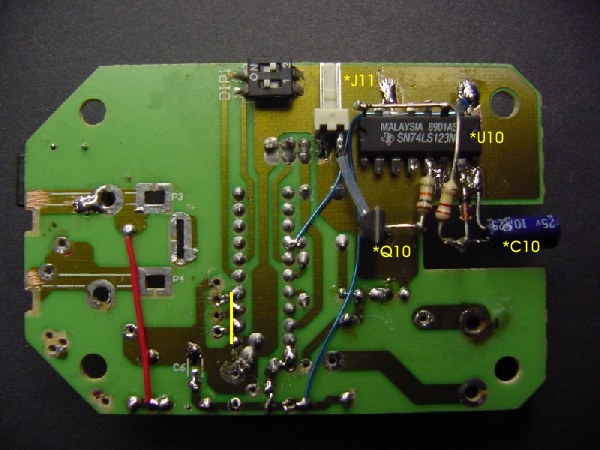 Bottom View of SYM-1 Remote Reset PCB The reset pulse circuit is in the lower right side of the schematic. It is made up of the 74LS123 IC *U10 and associated components *R10, *C10 and *D10. *U10 is mounted on the PCB by raising all pins upward except pins 6, 8, 9 and 14 which get soldered to the ground plane located below the IC. You will need to scrap off the protective coating on the PCB at these pins to allow proper soldering. Soldering these pins to the PCB ground also holds our IC chip down. All the remaining IC pins that get used become solder posts for mounting our support parts. Unused IC pins get cut off close to the IC. The 74LS123 is wired as a one-shot pulse generator. When it's input pin (P10) transitions from a low level to high level it will generate a positive output pulse (P13) for a period determined by the value of the components *R10 and *C10. In this case the pulse is about 1/2 second. So when we activate this adapter, turning it ON, this one-shot will generate the pulse. That pulse will then switch on the VMOS transistor *Q10 and it will pull-down the reset line that runs over to our SYM-1 computer. On the PCB bottom side picture is a small yellow line. I added that to show that I soldered a shorting wire to pins 1,2 and 3 of the PT2272-L4 IC to the ground plane that is right next to pin 1 of the device. Since I removed the channel switch PCB and wires before I started the modification I need to program which channel this adapter will respond to from the GE Smart Home Controller unit. Grounding pins 1,2 and 3 sets this adapter to channel 8. If I wanted to set it to a different channel I could wire it differently. I have a table of those setting in my other article on the RF100RXPS unit. I could have also added a PCB mounted BCD encoder switch and made it easily changeable. However, it was my desire to have my SYM-1 reset set to the last channel on my web controlled GE Smart Home. Lastly I need to wire the SYM-1 SBC board to bring the SYM-1 reset out to allow connection to the adapter. A Philmore 70-4852 two-pin locking socket, same as used on the adapter side, is installed onto the bottom of the SYM-1 PCB. Pin 1 of the socket is wired to pin 11 of the keypad connection pins as shown in the picture below. Pin 2 of the socket is bent downward and soldered to the SYM-1 ground plane. That grounded connection holds the socket in place, but you could add some hot glue over the backside of the socket to provide a more secure bonding to the PCB. Hot glue is easy to later remove if you don't want to make changes to the SYM-1 SBC that can't be fully reversed. 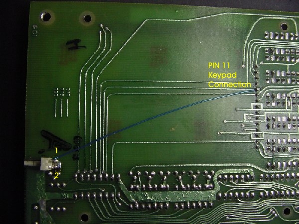 SYM-1
SBC Reset Wiring
Now all that is left is to package the
adapter into a new box. I had the small blue box lying around and
the adapter fit perfectly. The small helical antenna was gently
bent upward and protrudes out the top of the adapter box. I
wouldn't recommend using a metal box, but if you do make sure the
little antenna extends out of the box and does not come into contact
with the metal case.
Lastly a cable is made to connect the SYM-1 to the adapter. Length isn't overly important. Mine is about three feet long to allow placing the adapter in a position that allows trouble-free communications with my GE Smart Home Controller unit. Now if I'm on-the-road and need to reset my SYM-1 I just bring up my web control page and turn on OUT 8 and the computer resets. I can then go on working. Just as if using the computer locally and pressing the RESET button on the keypad. Remember turning OUT 8 off will do nothing to the SYM-1 reset line, so I can turn it off anytime in the future. 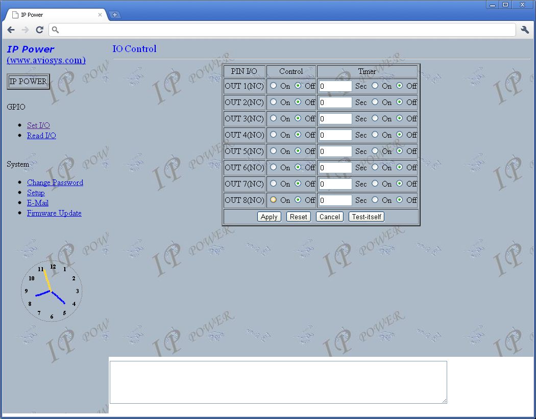 My
GE
Smart
Home
Remote Web page Control Screen
All
is
fine
with
the SYM world! The
reader should note that the output of the PT2272 IC (P13) could be used
to drive just about any other logic or switching circuit that could be
used as an output control for other functions. The limit is only
in your imagination.
Don, February 2011 |