| GE
Smart
Remote
Ethernet
Interface for GE Smart Remote Model RF2000KINPS Part of GE Whole-Home Lighting Control Kit 51151 January 2011 Updated: 26-Nov-2011 |
|||||||||||||||||||||||||||||||||||||||||||||||||||||||||||||||||||||||||||||||||||||||||||||||||||
 Here is GE's blurb on the control system: Control lights and appliances throughout your home from one central base station. Great for added safety and security.
I liked the system since the remote control
is very easy to
program and AC control receivers can be located near the items you want
to turn on remotely. I liked the fact that it uses a UHF radio
frequency control vs over the power line controlling like early X10
devices. Since I do a great deal of ham radio work I don't want
to add a bunch of additional noise onto my house AC power system.
So far I have not had any problems with interference listening or
transmitting with any of my radios using the GE Whole-Home Lighting
Control.
One word of caution, the GE control unit and the various outlet adapters have some construction quality issues. I mention these later in this discussion and on other pages here relating to these devices. Mainly the biggest problem area is with the multiposition selector switches as they exclusively use slider contacts that are poorly mounted onto the plastic switch thumb slides or rotary knobs. Often you will find a control unit that the lower AUTO/MAN/TIME SET/PROG slide switch does not function properly or the channel switch on any of the outlet adapters doesn't change channels (stays at channel 1). Both issues are due to the plastic hand selector has become detached from the contact wiper. Most times these can be easily repaired. I'll address these repairs later. I only mention this since I usually purchase these things off of eBay and the last complete home kit I bought had every one of these switches damaged. So obviously along the way someone put together a complete kit of dud devices. So GE took what could have been a very reliable series of products and chose to use a very low quality design for their slide or rotary switch assemblies. Having just used the GE system to turn on
all my outside Christmas
light this past year it got me thinking about updating my GE Whole-Home
system to connect into my home computer network, and also provide me
with the ability to control AC devices in my home when I'm away via the
internet.
Here's what I needed to do: 1) Modify the GE Smart Remote control unit to provide an interface that would connect to one of many of the current Ethernet I/O controllers on the market today. However, do no damage to the controller so that it can continue to function in it's normal manual and internal programming modes. 2) All control will be performed by emulating the On and Off button pressing for the eight remote channels. All other functions will operate as out-of-the-box. Also, those eight manually controlled channels will still function as before. Remember, do no damage! 3) Construct the external interface circuits to couple the GE Smart Remote to the Ethernet I/O controller. 4) Find a Ethernet I/O controller that would allow me to talk to the GE Smart Remote via a web based interface over the internet. About
the
GE
Smart
Remote
The GE Smart Remote is part of a kit called
the Whole-Home Lighting Control Kit (51151) which consists of the
controller unit addressed in this article. The kit also contains
two Smart Remote Plus (Indoor Outlet Adapter) receivers. In my
internet searches I have never seen the controller sold separately, but
only in this kit. Actually that's a good way to acquire the
control unit as most often the whole kit sells for about the same price
as the two included receivers or around $30 USD complete. Plus,
there is no reason you can not use multiple controller units in your
home. They will not interfere with each other, albeit the unit
that turns a light or other AC device ON will be the only one to
indicate that the channel is in the ON state. The control units
do not communicate with each other!
First let me start off by describing what I have found out about the GE Smart Remote model RF2000KINPS (part number that is on the underside of the unit). This remote controller transmits code bit data to receivers located within 150 feet. Most of the receivers either plug directly into any AC outlet (Model 51140) with in your home or via a short AC line cord (Model 51141) in the case of their outside versions. I use the outside versions to control my Christmas lights. Communication is performed over an RF link near 320MHz (UHF) with only about 3mW of power. Today's
consumer
electronics
are
often
controlled
by
some
form
of
computer
or
micro-controller
processor.
They
can
be
custom
devices
that
are
tailored
to a specific line or type of equipment. In the early
days of computer controlled devices, the product panel switches would
often be wired to directly change the state of an input to the
processor by either pulling it to a low or high logic level. This
worked fine when the number of control switches was small.
However, today we find that even things which were once controlled via
potentiometers (variable resistors) or variable capacitors are now done
through digital control. This fact combined with an increase in
the on-off or multi-position selections offered has increased the input
requirements on the processors. So what does a good design
engineer do? Well to eliminate having a separate processor input
for each switch they changed over to a matrix switch setup.
Basically we can look at such a switch matrix as a grid of wires
consisting of X rows by Y columns. We would have one switch
connected between any specific row and column. For example, lets
assume we
have a 2 X 2 matrix with the rows R1 and R2 and columns C1 and
C2. We can have four switches connecting the wires as follows
R1-C1, R1-C2, R2-C1 and R2-C2. Now if we connect the rows to an
output port on our processor and the columns to the processors input we
could turn on just one of the rows and then see if either of the two
switches are transfering that "turned on" signal over to our column
inputs. Then we could go over to our next row and again check
which switches are on. But wait I told you a switch matrix would
save us on processor I/O port lines! With a 2X2 matrix we would
still require four I/O lines to support four switches - That saves
nothing. True, the 2X2 matrix really doesn't save use
anything. However, what happens in a 4X4 matrix. Now we
have only four rows by four columns, but we can now support 16
switches. So eight I/O lines from our processor can control
double the amount of switches. Think about it, what if we had an
8X8 switch matrix? We would now be able to support 64 switches or
8 times 8! The number of supported switches goes up much faster
with each row or column we add to our switch matrix. Look at all
the buttons you have on your cell phone. Do you think each key
uses a unique I/O line into the processors that runs your phone?
Don't count on it - They are connected in a switch matrix system.
So
why did I provide this brief tutorial on switch matrixes? Well
count the switches on the GE Smart Remote. It has 27 individual
switches. Notice the OFF and ON for controlling the eight control
channels are actually two switches. One to turn a channel OFF and
another to turn it ON. Also, the four position slide switch is
actually four separate switches, i.e. one gets closed for each position
of the slide. Yes you guessed it, the Smart Remote uses a switch
matrix to read when a switch is being closed by pressing on the button
or by changing the slide position switch. Oh yes before I forget,
there are two switches on the under side of the remote that select the
House Code. That's just in case you counted and were only coming
up with 25 switches!
Opening the Cabinet
With
the
above
lesson
completed
lets
open
the
GE
Smart
Remote.
The
unit
top
and
bottom
halves
are
held
together
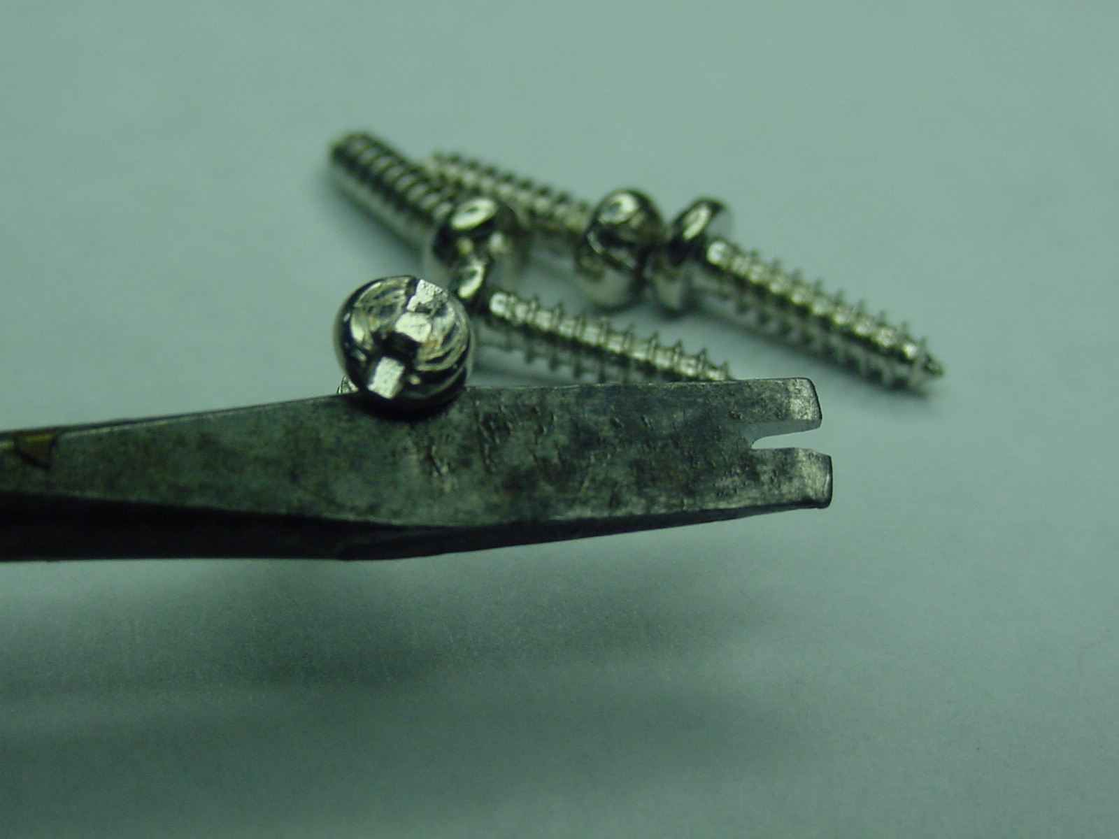
by five screws accessed
via the bottom of the unit. This is our first gotcha! GE
used tamper proof screw heads on these externally accessable
screws. Oh well I guess I should just give up now as they don't
want me inside. Yeah right! So first we will need to make a
screw driver that can remove the screws, unless you already have a set
of tamper proof screw drivers. The screws appear to be regular
straight-slotted, but on closer inspection you'll notice a little
extended dimple at the center of the slot. So I sacrified one of
my
"not so nice" screw drivers that fits the slot size and notched the end
of the driver with a cut-off blade on my Dremel tool. It only
took a second to make myself a tamper proof screw driver. Below
is a picture of the finished driver.
 OK
now
we
are
ready
to
remove
the
five
screws
holding
the
Smart
Remote
together.
we
can
separate
the
top
and
bottom halves of the unit. Be careful as the lower body
has the intergrated battery compartment with DC power leads connecting
to the upper portion of the case. What follows
is a picture of what is inside.
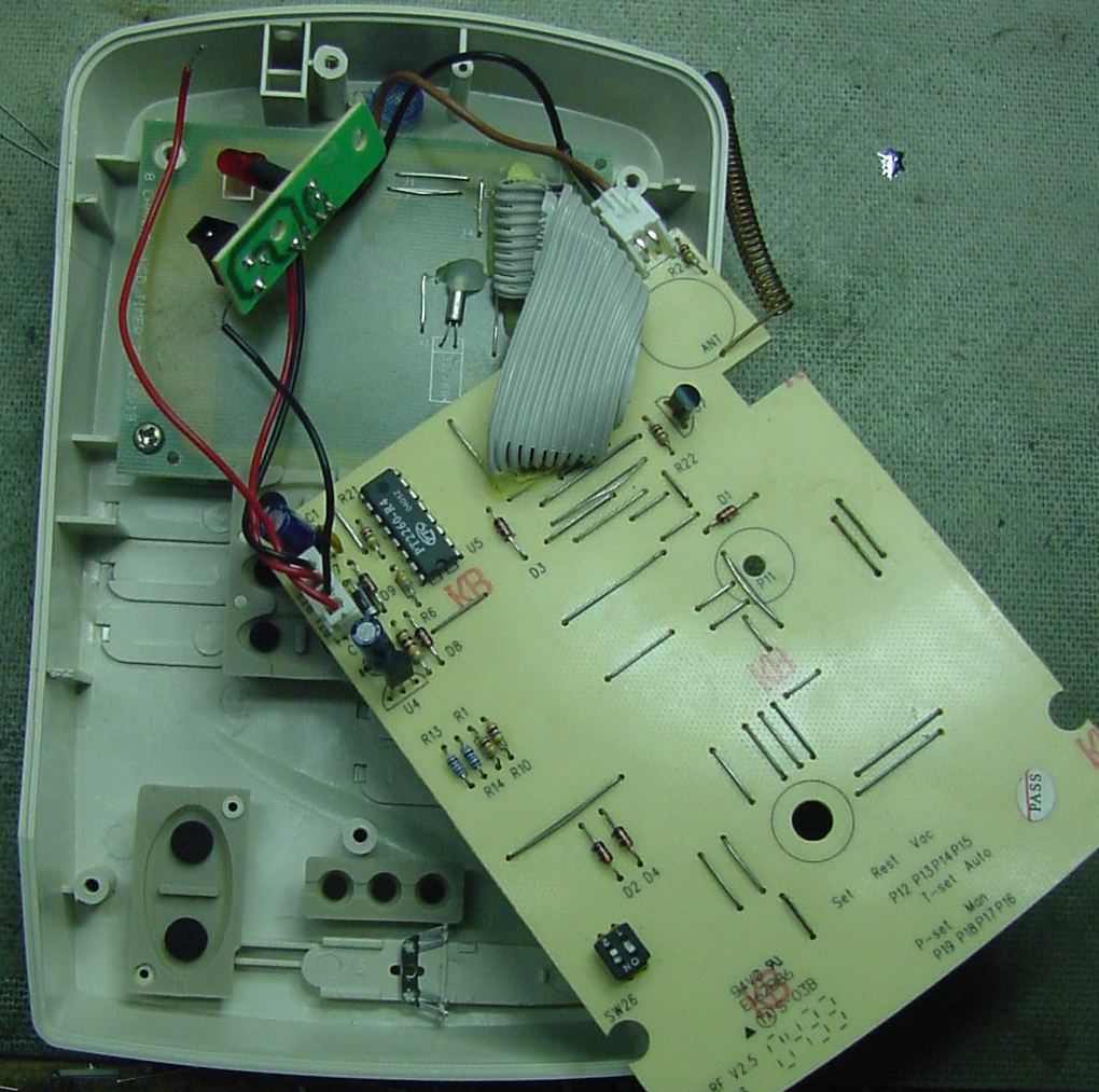 The screw labeled P11 will remove the main switch board. Notice I show pictures of this board removed, but to perform the modifications in this article you don't have to remove this board! You can also remove the screw that hold the LED and DC power input connector at the top of the unit. The big board is what I call the switch board since that is where all our switch contacts are located. You will notice that all the front panel switches are rubberized units with little conductive pads attached. Those pads short gold plated switch contacts that are located on the underside of the switch board. You may notice that I unsolderd the black and red DC power wires that originally connected to the underside cabinet pieces battery compartment. This just made it easy for me when I was tracing out circuit board connections (see below). To perform the required modifications to this unit shouldn't require you to removed those DC battery wires. The Switch Board
Some
notes
on
what
you
see
on
the
top
side
of
the
switch
board.
On
the
upper
right
side
is
a little helical coil that is soldered into
a hole labeled ANT. This is the antenna used to transmit control
signals to the remote receiver units. Later I'll describe my
removal of this antenna and the addition of an external antenna on my
unit to increase its range. If your already using one of these
Smart Remotes and have had no problems reaching all the receivers
around
your house you probably would not do this later modification. For
me my Ethernet I/O controller is in the basement of my house and I
needed to provide a better antenna system to communicate with all the
receiver units I plan on using.
The
two
position dip package switch on the lower left, labeled SW26, is the
House Code switch. The IC on the upper left is a PTC PT2260
Remote Control Encoder. This takes data from the units processor
(located on the LCD board) and
converts it into a serial data string (address/data and sync
bits). This data string is what gets transmitted to our remote
receiver units. The gray ribbon cable that is soldered onto the
board is the main communication cable to and from the processor-LCD
board. On the left side there is a four pin connector which has
our two battery DC power wires and the two DC power wires that come
from our AC adapter that plugs into that little board with the LED on
it. A warning note. The battery lines provide 4.5VDC to the
unit, but the AC Adapter provides 12VDC. That 12VDC gets
regulated down to 4.5-5.0VDC on the switch board. Notice all the
jumper wires on the top side of this board. Those will actually
be instrumental in our modification as they provide a means to connect
into our switch matrix.
One
note
of
caution,
the
slide
switch
can
be
seen
under
the
switch
board
has
a
little
contact
slide
assembly
that is attached by two
plastic posts. When I removed my switch board that contact
assembly fell off. That required me to melt those little posts to
secure the contact assembly back on. Again, you don't have to remove
this board to do the modifications.
Now lets look at the underside of the switch board (below). 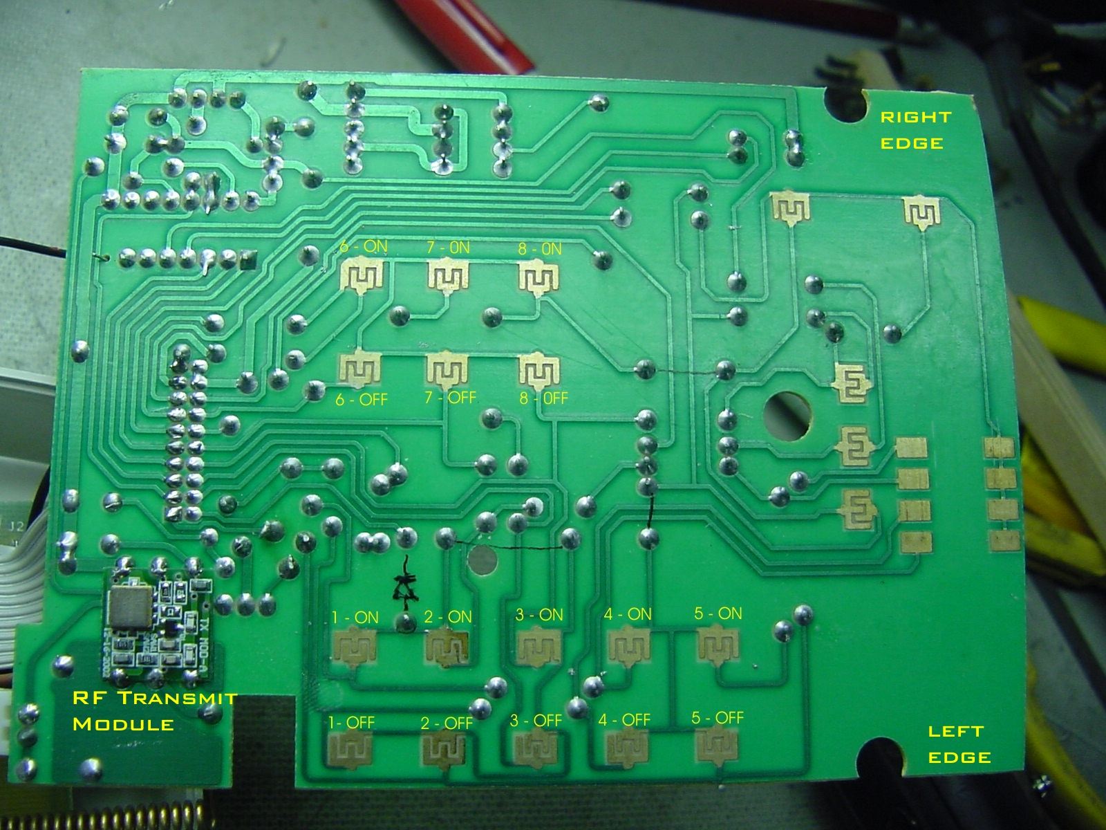 Since my goal was to simply emulate the
pressing of the On and Off channel buttons I need to find those switch
contacts on the bottom of the switch board. As you can see I have
labeled them in the above photo. As I indicated earlier when
talking about switch matrixes there are actually two switches per
channel. One to turn the remote receiver on and one to turn it
off. Since there are two contacts for every switch I had to
perform a trace of 32 contact connections within the matrix (8 channels
X 2 switches X 2 contacts). Below is my switch matrix analysis
table. The real important information on this table is what I
call the "Common Connection" This shows which of the 32 contacts
are either a common row or column in the matrix. Notice that I
did not do a full analysis of all switches on the Smart Remote since
there would be 54 contacts to analyze and since I had no interest in
those other switches why waste the time. The Common Connection
letters have no real meaning and are just a reference to determine
later which two lines need to be shorted to emulate a button pressing
on any of the eight channels either on or off.
So
what does this table tell us now? We see that for all the manual
channel ON/OFF switches we have nine common connections (A-I). Do
I have to know if these are row or columns? Not really. My
plan is to emulate the switch closer using relay contacts that get
driven by the I/O signals of my Ethernet I/O controller of
choice. You might ask could I perform these switch emulations
using an electronic switch, i.e. a transistor. The answer would
be yes, but then I would need to dig much further into the Smart Remote
circuitry to determine which of these letters were rows and which were
columns and then determine which are output and inputs from our
on-board
processor. Last I'd have to measure the control voltage levels to
determine what type of transistor to use. All of that is a great
deal more work than I wanted to do and a simple relay contact placed
across any of the channel ON or OFF connections would be much
easier. Plus it's safer as making one wrong move attempting
electonic switching could damage the Smart Remote processor.
Again let me remind you how much the the switch matrix will save us in connecting to a Ethernet I/O controller. I will only need to connect nine (9) wires into the Smart Remote unit to be able to emulate any of the 16 switches (32 switch contacts) on the front panel. For example, lets say I want to turn on all the remote receivers in my home that have lights or whatever set to channel 7. From my table I would only need to short (via relay contacts) the lines for D and I together and it would be the same as me pressing the channel 7 ON button on the front panel. Remember those wire jumpers on the top side of the switch board. Well those Common Connection points can be obtained from those jumpers. Below is another picture of the top side of the switch board with all those points labeled. The connection for "I" is actually one side of the diode labeled D3 on the board and not an actual jumper wire.  Now all we need to do is wire up
a cable that has nine wires to the A-I points shown. I had a nice
14 wire ribbon cable lying around that terminates into a 14 pin IDC
style connector. So when I construct my interface board that will
connect between my Smart Remote and my Ethernet I/O unit it will be a
simple thing to plug in. To use the Smart Remote as a standalone
unit, or as originally designed, I mearly have to unplug the cable and
I can move it anywhere.
The following picture shows the ribbon cable all wired into the Smart Remote. I used my handy Dremel tool to cut a small notch into the lower side of the Smart Remote to allow the ribbon cable to exit. Notice I used some hot glue to hold the ribbon cable securely to the inside onto the switch board.  Transmitter Module Before
I
move
on
I
want
to
mention
the
little
transmitter
module
that
is
on
the
underside
of
the
switch
board. If you go back a few pictures I have it
labeled on the picture of the underside of the board. This module takes the data from the PT2260
Remote Control Encoder IC and converts it up to our 320Mhz UHF
frequency. I couldn't read any
of the marking on this module so I can't provide more than what I was
able to measure using a spectrum analyzer in my lab. It's
not anything we need to
be concerned about since however the data gets modulated onto the RF
carrier it gets decoded just fine on the remote receivers. So why
worry about it?
Do you need a better Antenna? Before we button up the Smart Remote you
can now ask yourself if you want to add an external antenna. As
you can see in the previous picture I have added a BNC connector to the
side of my unit. A small length of coaxial cable is then run to
the hole where the original little helical antenna was soldered
into. Coaxial cable requires two connections. One
connection for the center conductor and a second for the braid.
On the underside of the switch board the braid would be connected to
the large PCB area directly under that large printed circle on the top
of the board (right above the ANT label). You could scrape
away the protective coating in that area and solder the braid directly
to that area. In my case a drilled a small hole in the center of
that area (about 3/8" above the ANT hole) and soldered my braid
connection through that hole. I still needed to scrape away the
PCB
protective coating around my new hole. Since I'm maintaining a
nice RF path via coaxial cable to the new BNC jack I could run external
coaxial cable to an antenna located a fairly good distance from the
Smart Remote unit. However, I'd not suggest going to far as small
coax can have substantial loss at 320MHz and this unit only puts out
around 3mW.
I opted to simply add a extendable vertical
antenna to the side of the
unit. For 320MHz I used a vertical set at about 26" (3/4
wavelength). Monitoring it on a spectrum analyzer connected to a
50 ohm load across the room I could see a vast improvement in the
signal strength using my new external antenna vs the original tiny
helical internal antenna. However, as I mentioned before, don't
bother with this antenna modification if your unit already communicates
well with all your home receivers.
Button up the Smart Remote
Once
the
nine
wire
control
cable
has
been
attached
to
the
switch
board
and
the
antenna
modification
is
made
(if
needed)
you can now reassemble the
Smart Remote. I figure if
you were able to perform the aforementioned modifications I really
don't need to tell you how to put it back together again.
About Ethernet I/O Controllers
Next I will describe the interface
circuitry and Ethernet I/O controller I am using to control my
Smart Remote. I do not
expect nor do I even
suggest that you use the same Ethernet controller I am using.
However, I will address a few items that should be universal when you
begin to evaluate them.
I
am
using
the
AVIOSYS
IP
Power
9212
Ethernet
controller
system.
This
comes
in
a
neat
little
package
of
three
small
boxes. One is the
9200 controller, a 9201 8-channel digital input box and a 9202
8-channel relay output box. There are two reasons I chose this
setup. First I bought it used very cheap! Second it has a
web-based control interface. AVIOSYS now has a new version called
the
IP Power Delux which uses the same I/O boxes, but a different
controller. They no longer support my older version and the best
technical support I could get from them is their suggestion I buy the
new box. So to say the least I don't think I will be using any of
their new stuff, unless I find it very cheap and used, haa haa.
Their web server software is all loaded in internal memory so the end
user
can't get to it. It's all JAVA code and from my initial
experience it is flaky. Plus, the web
control would not work when using Mozilla Firefox! Firefox is my
browser of choice. I'd always receive a "server reset" error in
Firefox. MS Internet Explorer and Opera both worked somewhat, but
often the frame loading would not complete (50% of the time) and I'd
have to refresh the
frame, sometimes multiple times, to get it to load correctly. The
Google Chrome browser was my life saver. It worked well right off
the bat.
So I have an instance of Chrome running with it's homepage set to the
9200's web server. I then just assigned the name "IP Power
Control" to a desktop shortcut icon. For now the browser
problem isn't a big deal, but it does point to some serious flaws in
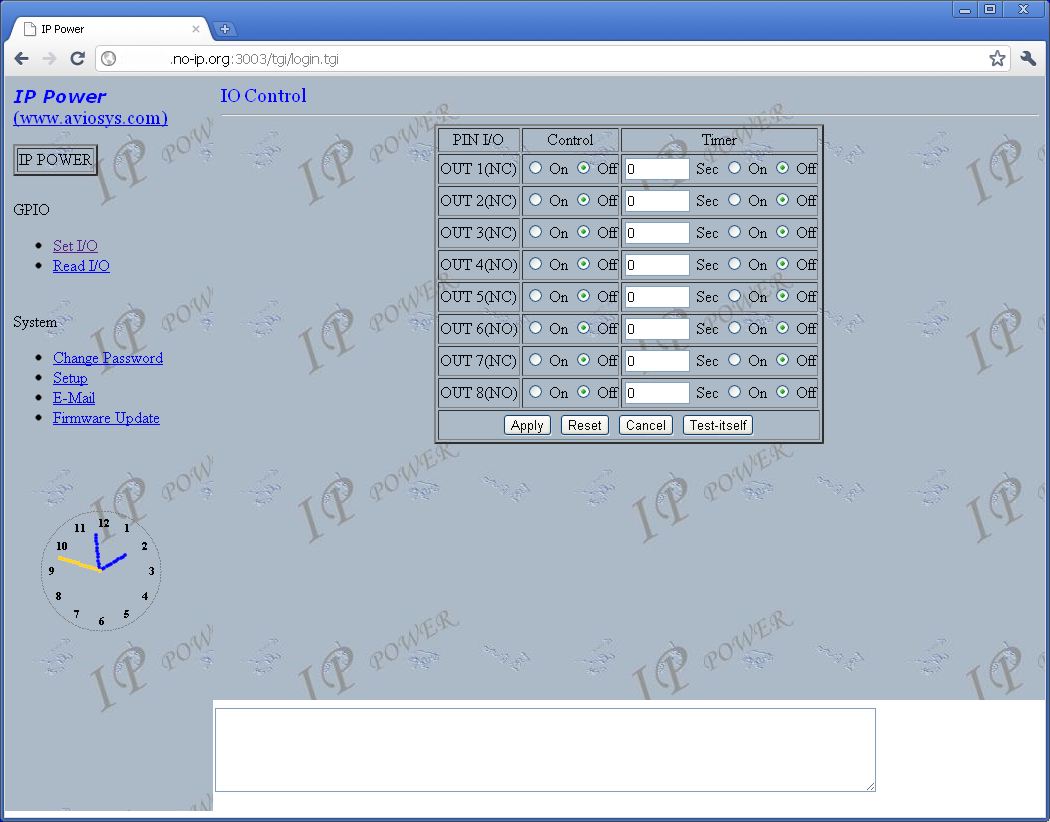
the 9200's webserver software! Another issue with
the 9200 is the output box is all relay output and they are fixed as
four NO (Normally Open) and four NC (Normally Closed). So when I
designed my interface between the 9200 and the Smart Remote I had to
work with those eight outputs as provided. Bottom line is the
controller works and I am able to control my eight Smart Remote
channels reliably. Below is a picture of my AVIOSYS web control
window for setting the eight output ports.
 For
me
I
can't
emphasize
how
important
having
a
I/O
Ethernet
controller
with
a
built
in
web-based
server
software.
I'm
not a programmer
and the thought of learning how to write a control program that could
be run via the internet would be a major undertaking. So I look
for
controllers that have decent web-based software and provide the
versitility to run the controller via the internet.
I
currently
have
two
other
items
in
my
home
that
run
via
the
internet.
One
is
a
ham
transceiver
that
has a dedicated
controller which is basically a remote Ethernet serial port with some
added capability to control specific functions required for remote
operation of transmitting equipment as required by the FCC. That
was a designed device specifically made for such a function and all the
control software is commercial and not written by me. A second
item that I just recently added is an older Lantronix MSS100 Ethernet
serial port server. I have that connected to an old 1978 vintage SYM-1 single board computer.
It works via a telnet connection, or
via a virtual serial port connection, so
I can work on this vintage computer from anywhere on the
internet. This leads me to another requirement for any future
web-based Ethernet controller. Make sure you can assign any IP
address to it and that it also offers you a choice of IP Port
assignment. If your going to do any remote controlling via
the internet your controllers will need to have IP address assignments
that agrees with the WWW.XXX.YYY.ZZZ setup you have currently running
in
your home (usually something like 192.168.0.ZZZ). The IP Port
number is the way to identify
your controller when you come in through the internet from the outside
world. I currently use the no-ip.org
free service to get me into
my different home controllers. The IP Port number is used to
identify which controller I'm working with when I access my home
network using my no-ip.org URL. I simple add a colon
followed by the port number (example http://mystuff.no-ip.org:3000) to
the end of the URL address in my browser and if the controller has a
web-based interface it will appear in my browser window no matter where
I am. Your router must be set up to direct that particular IP
Port (Port Forwarding) to your internally assigned controller IP
address. That's why you need
a controller that allows you to assign your own IP Port
number.
That old Lantronix server box is fixed at an IP Port of 3001.
Thankfully the other controllers, including the 9200 let me select a
new IP Port number. So my router is happy, as it prevents
entering the same IP Port assignments to different internal IP
addresses.
There
are
new
web-based
Ethernet
I/O
controllers
out
there
in
the
$75
range
that
have
more
digital
I/O
ports than my 9200 and they also
have analog ports as well! Plus, unlike my 9200 which limits you
to relay outputs, having direct logic level outputs would make
interfacing to the Smart Remote much easier. More on that when I
get into the interface design below. In the future I will
probably go to using one of the newer ones as time and money
permit. These devices are changing all the
time and becoming more powerful so the future looks bright for later
projects. I'm waiting for one that has
configurable and modifiable server webpages.
That way I could create simple web control pages that relate directly
to what I'm trying to control in my home.
GE Smart Remote Interface
Let's start off with a picture of my prototype of the interface between my
GE Smart Remote unit and the AVIOSYS IP Power 9200 Ethernet I/O
controller. The
prototype only controls channel 1 of the Smart Remote and will be
replicated on a final soldered together board to support all eight
channels.
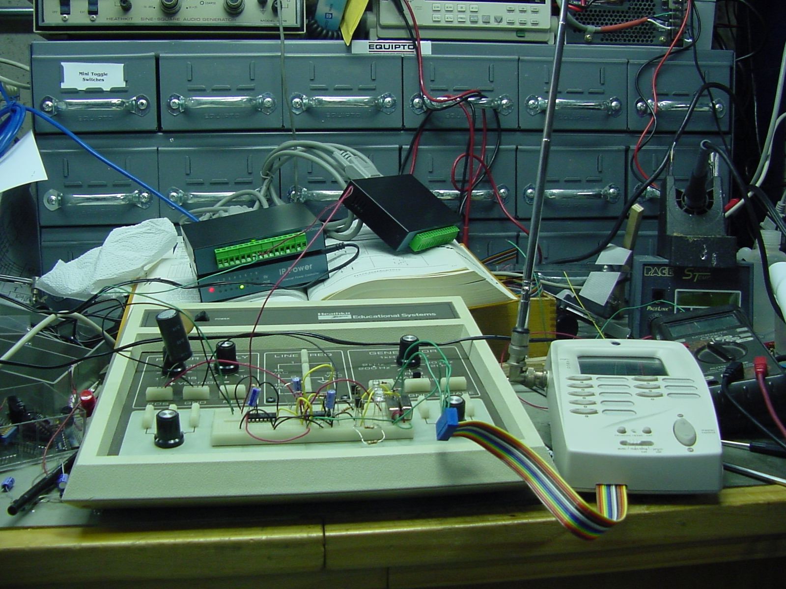 I
used
a
Heathkit
ET-3100
Electronic
Design
Experimenter
to
build
up
my
prototype
for
the
controller
interface.
This
is
the
only
way to
go when your experimenting with digital circuits! It has a
built-in dual polarity adjustable DC power supply, a function
generator, and enough prototyping area to do a fairly complicated
circuit. I
bought this in the Summer of 2009 for $10 at a ham radio
swapfest. A great deal!
Somethings to consider for this interface: 1) Outputs from my I/O Ethernet controller are relay outputs. Thus any interfacing will require cleaning up any transients, caused by relay contact bounce, from affecting the integrity of the logic signals. 2) Since my plan is to emulate the physical switch closer on the Smart Remote I will use relays to close those required contacts based on the Common Contact table and the nine control lines. 3) All I/O Ethernet controllers provide two states for any one digital output. This is true for a relay output like the 9200's, but also for any logic level output from other controllers on the market. However, since we are emulating pressing the keys on the Smart Remote we need to close the output relay for only a short time when our Ethernet controller output goes into an ON state and another relay to close for a like period when the Ethernet controller goes into the OFF state. Remember, the Smart Remote has separate switches for ON and OFF using different control wires. Well here is what I came up with:  Hey
BTW,
if
you
click
on
any
of
the
pictures
on
this
webpage
you
will
see
a
bigger
version
so
you can study the details on
any of them. Also, click here to download a pdf
version of the interface schematic above. Note the schematic only
shows the circuit for control of one Smart Remote channel. So
this circuit must be repeated seven more times, minus slight changes as
described later, to control all eight channels.
On the left side of the schematic is the connection to the output relay of the 9200. The capacitor C1 helps cleanup any small transients caused by the relays opening and closing in the 9200. In addition the 74LS14 U1 IC is a special Schmitt Trigger inverter. A Schmitt Trigger is a type of comparator. It measures the input to see if it is above or below a certain threshold. The threshold varies to make it less likely that the output will switch rapidly back and forth due to a noisy input near the threshold. So the combination of C1, R1 and U1 prevent any false triggering of circuits which follow it and is a mandatory requirement when working with any relay output controller. Without these components I was getting all kinds of false triggering. The next IC used is a 74LS123 Retiggerable Monostable Multivibrator. Now isn't that a mouth-full! Although on the schematic U2 is shown as two separate boxes it is really two multivibrators in one 16-pin IC package. It's just clearer to follow when they are drawn as two units. They are configured here to generate a short positive pulse at their outputs based on either a rising edge or a falling edge of an input waveform. This is referred to as a "one shot" configuration. Remember, our I/O Ethernet controllers only provide two states for any given single output. However, our GE Smart Remote will require separate switch closers to turn a channel ON and OFF. As you can see our 9200 uses a N.C. (Normally Closed) relay for output 1. That means when I turn that port bit to ON it will open the relay. That sets the input to U1 pin 1 high as it is pulled up to +5V via R1. The output of U1 pin 2 then goes low. Another inversion occurs in the next 74LS14 stage. So the input to the multivibrator would normally be low until we set our 9200 output 1 to ON. From a TTL voltage standpoint our multivibrator inputs will be normally around +5VDC when the 9200 output is ON and then around 0V when it is OFF. Going
from
0V
to
5V
is
a
rising
edge
and
we
see
that
the
lower
mulitvibrator
in
the
schematic
is
wired to produce an output pulse. When we go
5V to 0V that is a falling edge and the upper multivibrator will
generate a pulse. The pulse width is around 240 milliseconds
(approximately 1/4 of a second) which is equivalent to
an
equal length switch pressing on the GE Smart Remote. That pulse
length is determined by the 220K resistor and 3.3uFd capacitor.
Notice they are the same value for both multivibrators. The
diodes D1 and D2 are also important and don't leave them out as some
74LS123 data sheets will tell you they may not be needed.
They are needed!
So
now
we
have
separate
240mS
pulses
being
generated
on
the
opening
and
closing
of
our
I/O
Ethernet
controllers
output relay. Now we need
to use these pulses to drive a small relay that will short around the
existing Smart Remote ON or OFF switch and act to emulate those
switches being pressed on the unit. Remember we are essentially
wiring our control relays in parallel with the existing Smart Remote
switches. The Smart Remote switches are still 100%
functional! The 2N3415 (or any small switching NPN transistor) will
turn on during the pulse time and activate the relay (RL1 or
RL2). The relay can be any small 5V SPST relay. It does not
need to have high current contacts. I used some that I had lying
around. Mine had a coil resistance of 180 ohms which means they
will draw about 30mA of current when activated. You could use
higher coil resistance relays and they would draw even less
current. In the case of channel 1 on our Smart Remote the ON and
OFF relay contacts would connect to our C & B and A & B lines
respectively as per the previous table. Again we only have nine
wires coming from the GE Smart Remote labeled A through I. So
when we do all eight channels or 32 relay connections we will have
many lines that get shared across relay contacts. Like line B for
Channel 1.
You
will
recall
four
of
the
9200
controllers
relays
are
N.O.
(Normally
Open)
contacts.
There
are
two
ways
to
handle
that using my
interface circuit. One would be simply to swap the two relay
outputs. So the one labeled for the ON button would now be the
OFF button and vise versa. However, I chose to do it a little
different on my final 8-Channel interface board. Another way is
to invert the input to the multivibrators. So in the case of the
N.O. ports I will eliminate the second 74LS14 gate. The 74LS14 IC
actually has six inverters per IC chip. Four of my 9200 ports are
N.C. using two inverters and four are N.O. using only one. That's
a total of 12 inverters or two 74LS14 IC's. Even if I only used
one inverter per port it would still require two IC's so why not use
all the inverters. Also,
the
other channels will use other inverters in the 74LS14's so the IC pin
numbers will be different for those channels vs the schematic.
OK what if you have an I/O Ethernet controller that only provides TTL level digital outputs. Well that is even easier! You could connect it directly to the connection labeled TTL on the schematic. You would then eliminate the 74LS14's and the 10K and 3.3uF input parts too. So a non-relay output Ethernet controller would actually be easy to implement. I plan on using jumpers on my final interface board that will open the output from the last inverter stage and place a connection point on the board to accept regular TTL voltage levels. In the future when I buy a different Ethernet I/O controller I can use the same interface board by making some simple jumper changes. Completed Interface
Below
is
a
picture
of
the
completed interface.
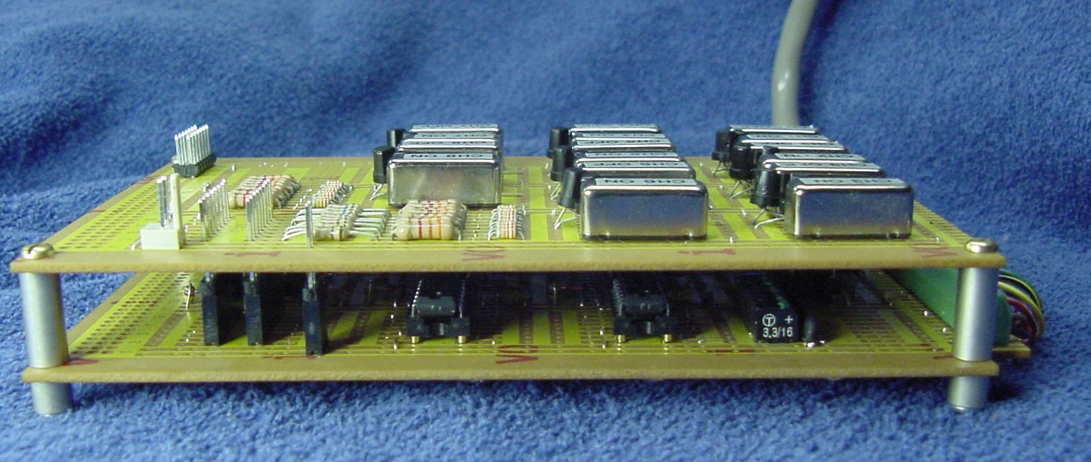 The final design uses two prototyping PCB's that measure 16cm by 10cm each. Underside connections are point-to-point soldered using Teflon coated wire-wrap wire. The top board contains all sixteen relays (channels 1-8 On and Off) as well as their associated driver circuitry. The lower board contains all the inverter and one-shot IC circuitry. The two boards are electronically connected via inline pin/socket headers (seen on the lower board left side). This makes for a very easy separation if repair is needed. The interface PCB assembly was mounted into a BUD aluminum die-cast enclosure. The final assembled GE Smart Home internet ready setup is shown here: 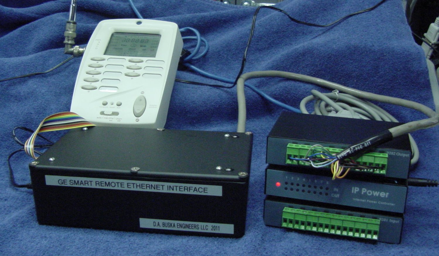 On
to
the
next
project.
12-March-2011 |