| Anatomy of the GE
Smart
Remote Plus Receiver and Conversion to General Purpose Relay Control Output Model RF100RXPS or 51140 February 2011 |
||||||||||||||||||||||||||||||||||||
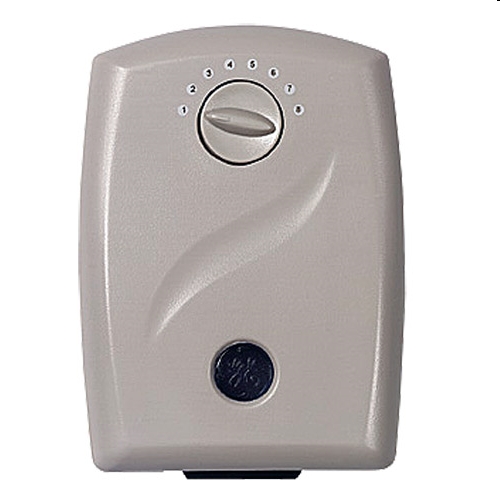 The picture above is of the original GE
Plus Receiver Indoor Outlet Adapter model RF100RXPS. This adapter
allows the direct 120VAC control of any appliance, light, radio or
whatever you want via the RF link to your home controller unit.
Anything up to 1200 watts resistive load can be sourced directly from
this units AC output connector. A recent project to modify one of
these adapters to provide a remote reset for a vintage SYM-1 computer
had me ripping one open to trace the schematic and make the required
changes and additions to facilitate my new use. In this document
I address a slightly different modification, which is much easier, to
simply change the output to a general purpose normally open (N.O.)
relay output. Thus the reader could use this remotely accessible
relay to control other items around their home that require a switching
of lower voltages or even higher DC voltages perhaps.
Here's what I needed to do: 1) Determine how to open this darn unit. 2) Trace out the circuit and explain how it works. 3) Describe the changes to convert this to a generic N.O. Relay remote control box that will still work as original as one channel in the GE Smart Home system. Opening the Adapter Cabinet
Opening the cabinet wasn't as easy as I
would have expected. In fact I'm not sure how to do it without
damaging the case a little. The enclosure is held together via
the top and bottom ends and in-order for me to get it opened I needed
to cut into those areas with my Dremel tool and a cut-off blade.
Here is a picture of the enclosure opened up:
 If
a
reader
determines
a
way
to
open
this enclosure without damaging it
please let me know and I will provide those instructions here.
For now you will probably need some glue to get things back together
once you have made the required modifications. There are three
circuit boards inside the unit. The large board contains the GE
remote receiver module and all the control circuitry. The little
board on the lower left contains a surface mount LED that
lights when this adapter is turned on via the GE controller unit.
The other small board above the LED board is the channel selector
switch board. GE went all out to make the channel selector
switches in their adapters about as cheap as possible. On the
many units I own it is this selector switch which is often
the cause of adapter failure, with the output relay coming
in
second. What happens is the little shorting contact assembly that
is rotated via that front knob often falls off and no longer makes
contact. In that case
the adapter still works but you will discover it only works on Channel
1. As you will see later, when I describe the circuit, if
their is no contact being made in this selector switch it will be
interpreted as channel 1 by the internal decoder.
Let's have a closer look at the main circuit board. 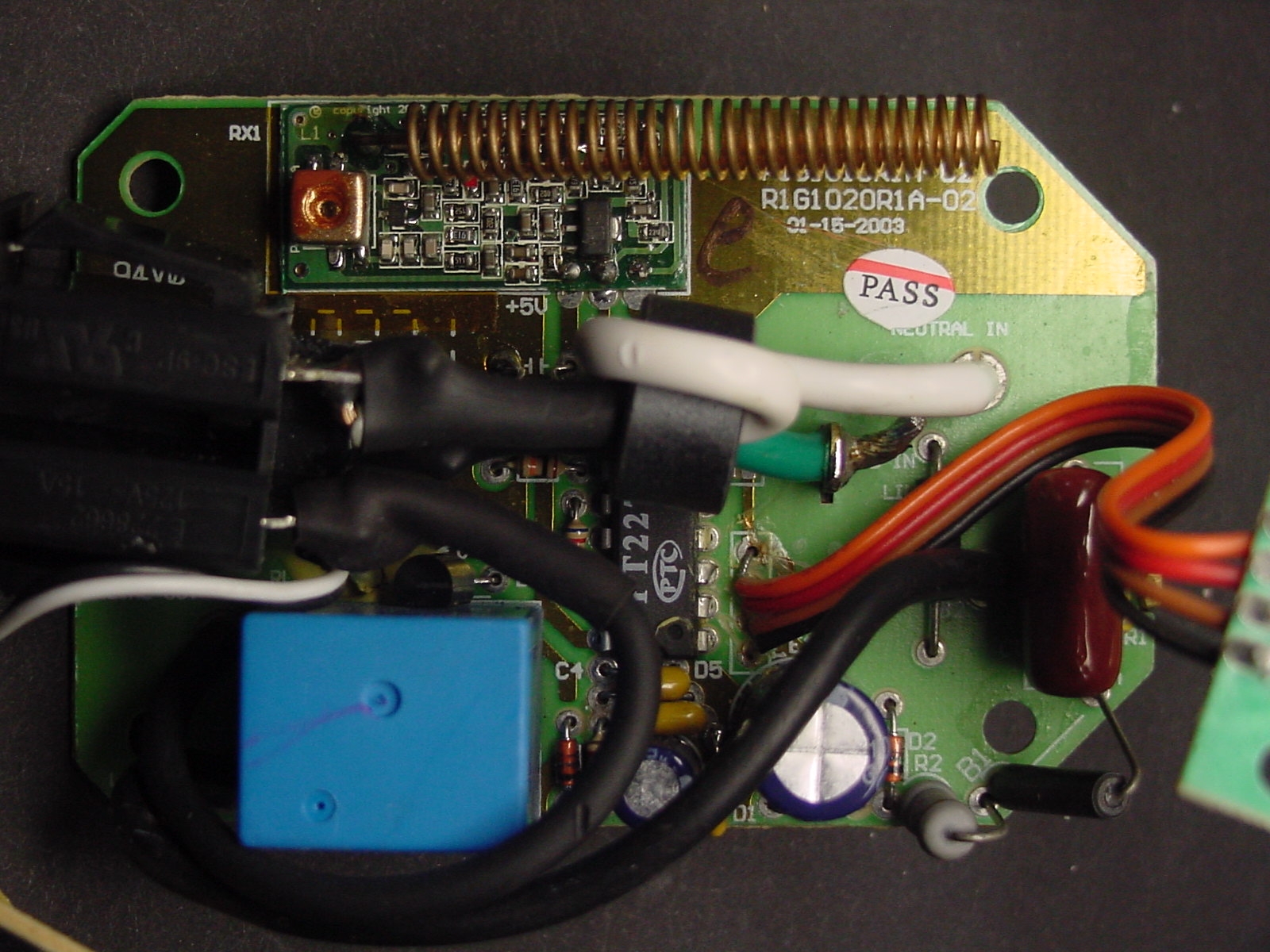 The AC input, the connector that plugs into the wall outlet, is located on the right side under the circuit board. The AC plug prongs solder directly onto the circuit board. As you can see the Green (Ground) and White (Neutral) wires connect directly to the AC output outlet that is on the left hand side of the picture. It becomes obvious that this adapter switches only the Black (HOT) wire in our AC line. It goes from the AC input plug to the lower left side of the circuit board next to the small blue cube. That blue cube is the control relay that connects our HOT lead to the output outlet when this adapter is activated by our GE controller unit. The other black lead on the left side of the relay can be traced to the output relay. GE Smart Remote Plus Receiver Circuit
Below is the schematic diagram of the GE
RF100RXPS outlet adapter. Please note you can click on the
schematic (and other pictures on this web page) to bring up a larger
view. In addition you can view a pdf version of the schematic by
clicking here.
All part identifiers are those
that are silkscreened on the printed circuit board.
 The
adapter
is
not
a
complicated
unit.
Let's
start at the upper
left. That is where the AC arrives from our home outlet. As
you can see the Ground (GND) and Neutral (NEU) lines run directly to
the output AC outlet that is located on the devices bottom when it is
plugged in for use. The neutral is also connected to ground in
our circuit through a small inductance of what is known as a ferrite
bead. A ferrite bead is a passive electric component used to
suppress high frequency noise so it can not enter, or leave, our
adapters circuitry. As far as our 60Hz AC voltage
entering the adapter the ferrite bead looks like a direct connection
and does not affect it at all. Our HOT AC line connects over to
one of the poles (contacts) of our control relay RL1. This HOT
lead will also supply the operating voltage for our adapter. The
two resistors R1 and R2 along with the capacitor C1 make up a voltage
divider
circuit to drop down our 120VAC line voltage to an acceptable level to
operate our adapter. The negative half of this lower AC voltage
is chopped off by the diode D2 (sent to ground) and the positive half
is rectified by the diode D1. The electrolytic capacitor E1 and
capacitor C2 filter our pulsating DC into a smooth ripple-free DC
voltage that is around 24VDC which is used to activate the
control relay RL1 as I will describe later. The 24VDC is
connected to resistor R3 which drops it to approximately 5VDC to supply
our
Remote Control Decoder IC (PT2272-L4) and our receiver module
RX1.
GE was very good about providing additional distributed capacitors,
C3,E2 and C4, throughout the circuit board to keep any voltage ripple
and transients from being propagated on our control circuits power
source.
The Receiver module (RX1) is located at the top of the adapter main board as shown previously. Communication from the GE Smart Home controller unit is transmitted via a 320MHz RF link (UHF) at only around 3MW power. The receive adapters, like this one, all contain little receivers tuned to that same 320MHz frequency and they demodulate the digital coding that is superimposed on that RF signal. That spring device that is attached to the RX1 module is a helical wound antenna. The demodulated data is supplied to the remote control decoder IC PT2272-L4 via pin 14 (DIN). The PT2272 is produced by Princeton Technology Corp. in Taiwan. If you review my other article on the GE Smart Home controller unit you will read that it uses a matching encoder IC PT2260. Our decoder IC will respond to any ON or OFF commands being sent by the controller unit if we are set to the same Home and Channel settings encoded into our received data string. As you can see the PT2272 has address lines that provide the input to our decoder as to the selected Home and Channel we have this adapter set to. The Home setting is via a two small switches that are located on the back side of the adapter (wall side) and are accessed through a small removable cover. The channel selection is done via that front panel switch labled 1 to 8. As I mentioned previously this channel selection switch is a weak point on these adapters and often are the cause of failure. A knowledgeable person could repair the switch in most cases, but if yours works don't detach that switch circuit board from the front cover piece. The switch is set up to provide a binary coding to the address lines A0 through A2 on our unit. It's actually a complimented logic binary. Here is a table that shows the logic levels on those address pins for the different channels.
The switch (SW) will ground the pins that are represented as a 0 in the table above. If this switch contact assembly fails, often it falls off behind the plastic switch knob, all the pins will remain ungrounded and thus we will always be selecting channel 1 no matter where the front knob points. So now if our received and decoded signal from the home controller unit agrees with the Home and Channel selection applied to our PT2272 IC it will respond to any ON or OFF command. When an ON is received it will set the output data pin D0 (pin 13) to a high logic level or approximately 5VDC. When it receives a OFF signal it will set that same pin to a low logic level or below 0.8VDC. The D0 output is a latched output and remains in its ON or OFF state until changed by our GE Home controller or if the adapter loses power. When it is set ON the 5VDC will drive the transistor Q1 to an on state. That will allow current to flow from the collector to emitter of the transistor and complete the circuit for the relay RL1's coil. Thus the relay will close its contacts and the HOT AC lead from our home outlet will be connected to the HOT lead of our adapters AC output outlet. Our connected AC device will turn on! Also, notice the front adapter LED is also part of this Q1 current path and it too will light to indicate the adapter is in the ON state. Once an OFF command is received by the adapter the D0 output goes low and our transistor Q1 turns off. Thus we no longer have a closed current path for the relay and LED and as a result the relay opens and the LED goes off. We no longer have the HOT lead connected to the adapters outlet and our connected device will turn off. That's the operation in a nut-shell. Converting
your
Adapter
for
Relay
Output
Control
It might seem strange to use an AC outlet to act as a connection for the relay closure and I would agree. But this describes a cheap and easy method to achieve this end. I will have another page on this site that describes my conversion of this adapter to provide a TTL logic level reset control for my SYM-1 computer. In that case I completely repackaged the original adapter, even to the point that it no longer even really needs an AC power source. If properly modified we would no longer need the relay and thus the only circuitry would all operate off of 5VDC and could feasibly work off battery power to supply the RX1 receiver module and the PT2272 decoder IC. The GE Smart Home controller is a fun and cheap unit that opens up a whole world of remote control around the house. I hope others will find these series of articles useful/ |