East Side
Updated 21-June-2026
| This operating position is actually
attached to the two station setups labeled North and
South Side, shown elsewhere on this site. If you
would, consider this position as being the bottom of a
u-shaped desk arrangement with those two aforementioned
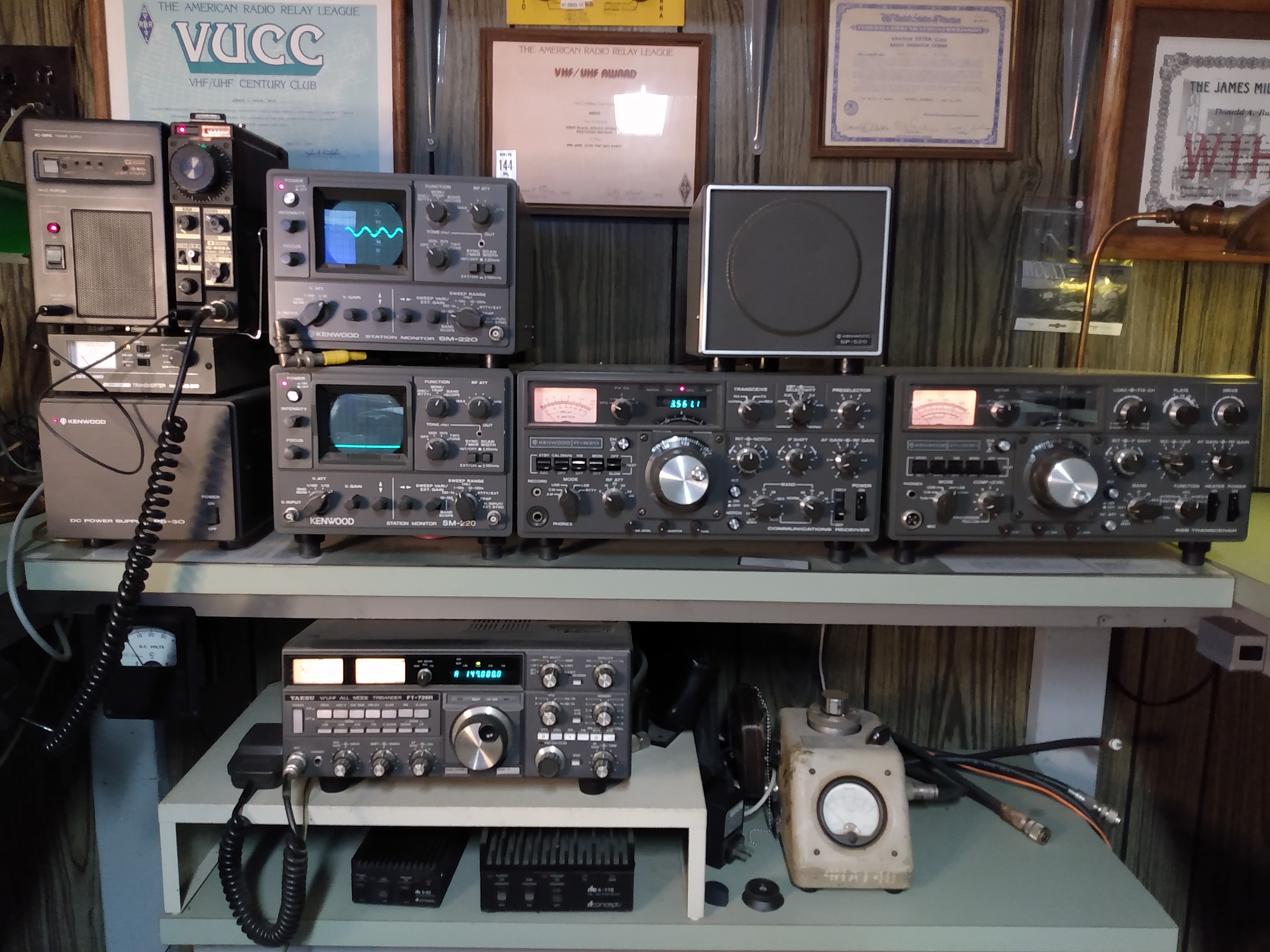
desk setups. Lowest Shelf on above picture: Yaesu FT-726R triband VHF-UHF radio covering the 50MHz/144MHz/432MHz bands. This is my VHF/UHF SSB/CW station. On 2 meters I have currently worked over 35 states. Any amplifiers on these bands are all various solid-state brick amps. 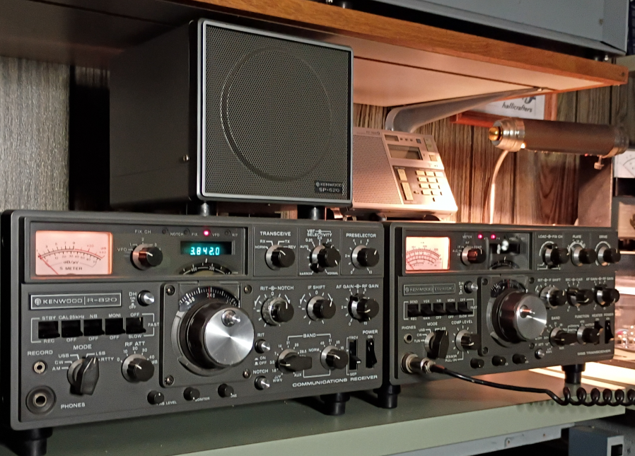 Left Click on Image for Enlarged View & Click Back Arrow to Return Desk Level Shelf: This is referred to as a Kenwood 8-Line. Most of this equipment is from the later half of the 1970's. Consists of R-L, the Kenwood TS-820 HF transceiver and next to it the matching R-820 receiver. This later pair can be operated in full transceiver mode with the TS-820 working as the transmitter and the R-820 as the receiver. This is probably my most advanced receiver in the shack. This R-820 is fully decked out with all the available IF Crystal Filters. What makes this receiver special is it has adjustments for IF level Notch Filtering, Passband Shifting and VBT (Variable Bandwidth Tuning). Essentially this receiver can remove just about any surrounding interfering signals residing near the desired signal you are receiving. Kenwood used the exact same front panel aluminum castings for the TS-820 and R-820, but as expected their knobs and switches serve different controlling functions, in most cases. For an purely analog receiver, exception for the digital frequency display, I have never used another receiver with the versatility and signal processing capability of the R-820! Rounding out the Kenwood line are two SM-220 monitor scopes. One is connected as a frequency domain Panoramic Display (BS-8 Option) which is essentially a spectrum analyzer to display the band around the current listening frequency. This Pan display allows you to view the band activity around your received frequency (+/- 100KHz) or a closer in sweep to view the received signals spectrum (100hz min). Outside of a modern SDR (Software Define Radio) with their spectrum displays this was not a common item in the 1970's, or prior. The second SM-220 is connected to the TS-820 RF Output, to monitor its transmit time-domain output waveform. As a speaker for both the TS-820 and R-820 I use one Kenwood SP-520. On the left side of this position is my ICOM IC-202A 2 meter SSB/CW low power transceiver connected to a Tokyo HY-Power HX-240 HF-Transverter. I talk about this elsewhere on my site. This little VHF transceiver becomes a full (Pre-WARC) 50 watt HF SSB/CW station utilizing the HX-240 to move it's operation down to the HF bands. Above the Kenwood 8-Line are two shelves that contain primarily my antenna matching units. 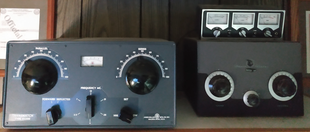 Left Click on Image for Enlarged View & Click Back Arrow to Return Top Shelf L-R: The Millen 92200 KW Transmatch is used with coaxial line antennas when needed. Immediately left of the Millen is a P&H AR-1 Coaxial Transfer Relay to allow bypassing the Millen Transmatch. The AR-1 was originally designed to insert an amplifier into the transmission line from a transmitter before internal bypass relays were incorporated into amplifiers. In this case the Millen 92200 does not contain a bypass relay either and the AR-1 serves that function here. On the right is a Johnson Kilowatt Match Box Model 950-30-3 which is used exclusively for a Full Wave 80 Meter Loop antenna feed with 450 ohm balanced ladder line. Lower Shelf L-R: We start with part of my earlier mentioned VHF to HF Transverter station here being the HX-250 Transverter powered by the Kenwood PS-30 below it. In the middle is a Micronta 21-522 500W Power/SWR/Modulation meter. The later is a relatively low cost meter ($34.95 in 1978), but surprisingly accurate! On the left is a Homebrew KW Transmatch that does contain an internal bypass relay. This transmatch uses the pi-network configuration with a roller inductor instead of the switched inductor used in the aforementioned Millen Transmatch. All my antenna transmission line feeds are located behind the wall. A wall mounted coax switch, located above the 21-522 meter, is used to select one-of-six antennas plus one-of-six rig positions. The knobs for the antenna switch are located on the wall below antenna tuner shelf, but all the actual coax cable connections (the switches themselves) are on the back side of this wall - out of sight! Only the final coax feeds enter the room at a point nearest the radios they support, where they are not visible to the operator. The Micronta meter described previously is in line between the antenna and rig sections of the main coax switch. Thus, the 21-522 is active for all tuners or any other antenna selected. |