| Yet another Drake TR7 X-Lock Implementation Creating a Reverse Illuminated Meter with X-Lock Indication |
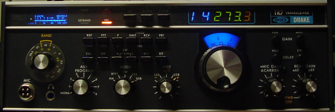 July 2011 A recent addition to my Drake TR7 was the Cumbria Designs X-Lock frequency stabilizer. To quote Cumbria's website, "the Cumbria Designs X-Lock takes a fresh approach to traditional frequency stabilizer design by employing modern microcontroller technology to perform frequency measurement and computation of drift correction signals." Thankfully I was able to learn a great deal about installing the X-Lock from the experience of others. Marinos, SV9DRU has an excellent guide to using the X-Lock in the TR7 transceiver. There are also some great directions provided by Ron, WD8SBB on the web. The intention of this dissertation is not to reinvent what has already been achieved by those who came before me, but to provide a few new ideas that I used when installing my X-Lock. My most significant change was a rebuild of the original TR7 meter into a reverse scale illuminated design with an integration of the X-Lock tri-color status LED right into the meter. As any TR7 user knows the original meter is a black (and some red) printed scale on a white semi-transparent background. The white area of the meter is illuminated blue by a standard light bulb and a blue gel over the front of the meter. Or for some users, including myself, we have changed to using blue LED illumination of the meter. With the installation of the X-Lock I saw the opportunity to test an idea that was brewing for some time. As a result I've designed a reverse lighted meter, in that the meter scale background is black and the scale and scale labeling are back lit. The X-Lock status LED was a natural inclusion for the new meter design. Other implementations have used the FIXED light indicator area (see links above) to provide a place to install the tri-color status LED. This is a great place as very few people actually use the fixed frequency option on the TR7. However, I opted to do no harm to that FIXED indicator and instead mounted the X-Lock status LED behind the rebuilt meter in a dedicated area. A picture is the best way to show what I have done. So here it is: 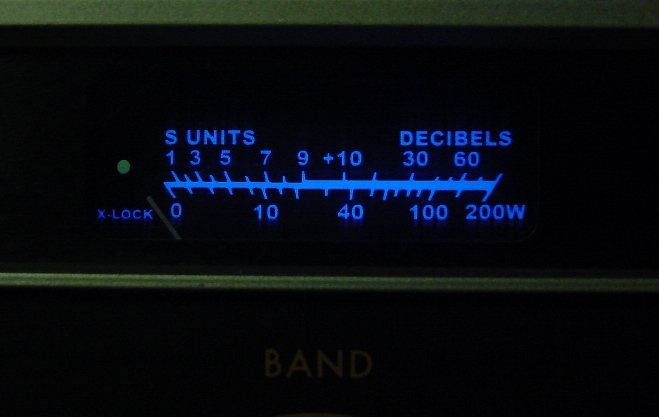 New Drake TR7 Meter with X-Lock Indicator Rebuilding
the
TR7
Meter
First a warning! Opening up
this meter or any electro-mechanical meter is not for the
inexperienced. These are extremely delicate devices. I
would have been very hesitant to do this rebuild if it had not been for
the fact that I had a spare TR7 meter in my junk box stock. So I
was all prepared if I did any damage I'd still had the ability to
return to the original meter. Thankfully the rebuild went
smoothly and I still have my spare meter.
Step 1: Remove the
Meter
Remove the TR7 top and bottom
covers. Remove the
two plastic end caps from the sides of the front panel, and
the BAND switch knob. The knob is held on via one straight
slotted screw. Remove the two screws holding the band switch
shaft detent to the rear panel and slide the bandswitch shaft to the
rear to just clear the front panel. Under the end caps are three
screws on each side
that hold the front panel to the internal frame assembly. Drake
used slotted counter-sunk screws and they have very little slot
depth. Try your best to get a screw driver that fits them well as
it is easy to damage those slots. I have since replaced those
4-40 screws with new versions that have deeper Phillips
heads. You can remove just the top two screws from each
side and tilt the front panel forward.
From the top of the radio remove the DR7 digital display board. If you've never removed that board consult the TR7 Service Manual for the procedure. I believe you can download this service manual online. If your installing an X-Lock and you don't have the service manual yet, get one - you'll need it! I tilt the top side of my front panel slightly forward when removing the DR7 board as it provides clearance for the frequency display sub-board allowing the DR7 to be pulled straight up out of the radio. With the DR7 out of the radio the front panel can now be tilted further downward once the BAND switch shaft is clear of the front panel. If you need more room to access the meter area you could remove the remaining two side screws which will allow pulling the front panel forward a little as well as the tilt down mentioned previously. Be careful that you clear the BAND switch shaft before you start tilting the panel. You don't want to damage the band switch wafers that are attached to the long switch shaft. Repairing the band switch assembly is not something even I want to attack - Be Careful! Here is what it should look like with the front panel properly pull away from the chassis frame.  TR7 Front Panel Forward for Meter Removal Unsolder
the
two
leads
that
attach
to
the
meter.
Write
a
note
so
that
the
leads
are
returned to the proper meter terminal when the meter gets
reinstalled. The disc capacitor can be left on the meter!
Remove the two screws holding the meter mounting bracket that are below
the left and right sides of the meter. You should now be able to
remove your meter safely.
Step
2: Opening the Meter - Scale Removal
 Open Meter with Scale Removed You
can
see
the
remnants
of
the
old
glue
that
held
the
original
scale
on
its
lower
corners. You should now close up the meter case to
protect the meter movement and needle from being damaged.
Step 3:
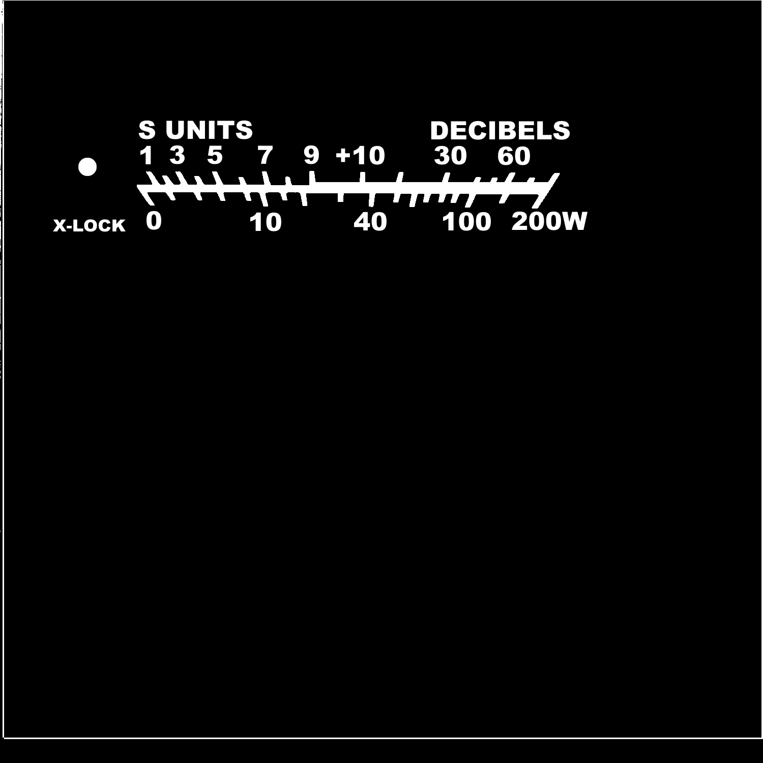
Creating a New Meter Scale
I computer scanned the original
scale and made all the required changes in Corel Photo 12. You
can download the scale jpeg file here.
Here
is
what
it
looks
like:
 New Meter Scale Recall the original Drake meter
had some red color labeling for the dB numbers above S9. For
those
who have converted to blue LED back-lighting you may have noticed that
the red turns black when illuminated by a pure blue LED. This
would be true for my reversed back-lighting also. Instead I
modified the main scale line to be slightly wider above S9. I
have also eliminated some of the meter scale numbers as I felt the
original was just to crunched. It is obvious, at least
to me, what each scale tick indicates even without each being labeled.
There was enough space on the left side of the original scale to add
the label for
X-Lock and a small round dot, about 3/32 diameter, above that
label. This dot is where the tri-color X-Lock status LED will be
mounted behind the meter. That dot will glow red, amber or green
when the X-Lock is operational.
Now we need to print the new scale out on some transparent sticker material. The type is not important as long as it is transparent or clear! I printed out my scale on a laser printer, a Brother HL-4040CN. You can try a inkjet printer if you like, but I'm not sure how good it will work. One thing I've noticed is that even with a laser printer the black is never black enough! If you print out the scale and hold the results up to a light you will see that some of the light will still get through the black colored areas. I used this same method years ago to make photo-masks for doing home printed circuit boards. That is when I discovered that a single run through the laser printer did not make the black area fully opaque. However, if the artwork is run through the printer twice it become very opaque! So you will need to run the sticker paper through the printer twice. This is where a cheap inkjet may have a problem. Naturally if you print it twice both images must line up exactly. I've found that laser printers are usually better at lining up on over printing than inkjets, but if that's all you have give it a try. Here is what it looks like out of the printer. Printout of New Meter Scale In my example above, I printed the
scale at the center of the page out twice first and they did not line
up very well.
So I moved the design up and over on my page and did another dual
printout and that one turned out excellent. I would recommend
only printing the new design out once per sticker sheet. If the
second printout does not line up you can move it on the page and try
again. In most cases you should be able to fit six to eight tries
per
page. Thus you save on sticker paper as you will only need to
repeat the trial until you have two successive printouts that line up
on
top of each other. As you can see I was able to get good lineup
on my second trial.
Now you will need to find some semi-transparent white plastic material to create the new meter scale. I search around the house and found a plastic packing container for my old Kensington Trackball mouse. This was a formed plastic where all the pieces of the trackball were held when originally packaged and boxed. Thankfully the sides of this formed enclosure were a nice white semi-transparent material. I cut out what I needed to make the new scale. Below is a picture of the original scale and my new replacement scale material cut out to match the original. 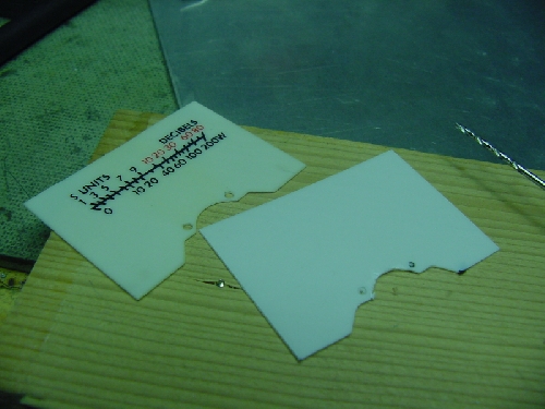 New Meter
Scale Material - Cut to Match Original
Next the new meter scale sticker
is applied to our scale material. It is very important that the
placement of the sticker lines up exactly where the old scale was so
that the meter pointer swing is the same, i.e. zero and full-scale
indications are in the same place as with the original meter
scale. Sticker placement is thus critical! You will trim
off any excess sticker that extends beyond the edges of the backing
plastic.
Since we are now using a black background meter scale it might be advisable to change the color of the meter pointer needle! I was able to slide a piece of soft rubber under the needle to hold it stationary and I then gently scrapped the old florescent red paint off the needle. Next I repainted the meters needle with Testers white model paint. As I warned before, damaging this very light aluminum needle could damage your meter and end your project. I used great care scraping off the old needle paint and painted two very light coats of white paint on the needle as to not add excessive weight or more weight than was added by the original paint to the needle. Again, I lucked out and it went very smoothly, much more so than expected. With the pointer needle repainted the new scale can be placed into the meter. Again, be careful when working around the pointer needle. I used a couple of drops of rubber cement under the new scale to hold it in place. Close up the meter and we are now ready to paint the outside of the meter. Step 4: Painting the
Case
Since we are now reverse back lighting the meter, i.e. the light shines
through the scale and lettering, we will need to paint all other light
entry points black. Again, I used Testers model paint.A little note here. I think Drake made a mistake when they cut the hole for the meter in the aluminum piece that slides in behind the clear Acrylic panel at the top front of the radio. If you look closely at the meter the top edge of the meter cover is visible. Drake should have made that cutout a little less tall so that we wouldn't see that edge. Since we now want to prevent all back lighting from leaking in on the sides of the meter we will need to paint the full meter case black, including the aforementioned top edge. The only areas that will not be painted black are the front window area and the area behind the meter scale on the back of the meter. Below is a picture of the painted case. 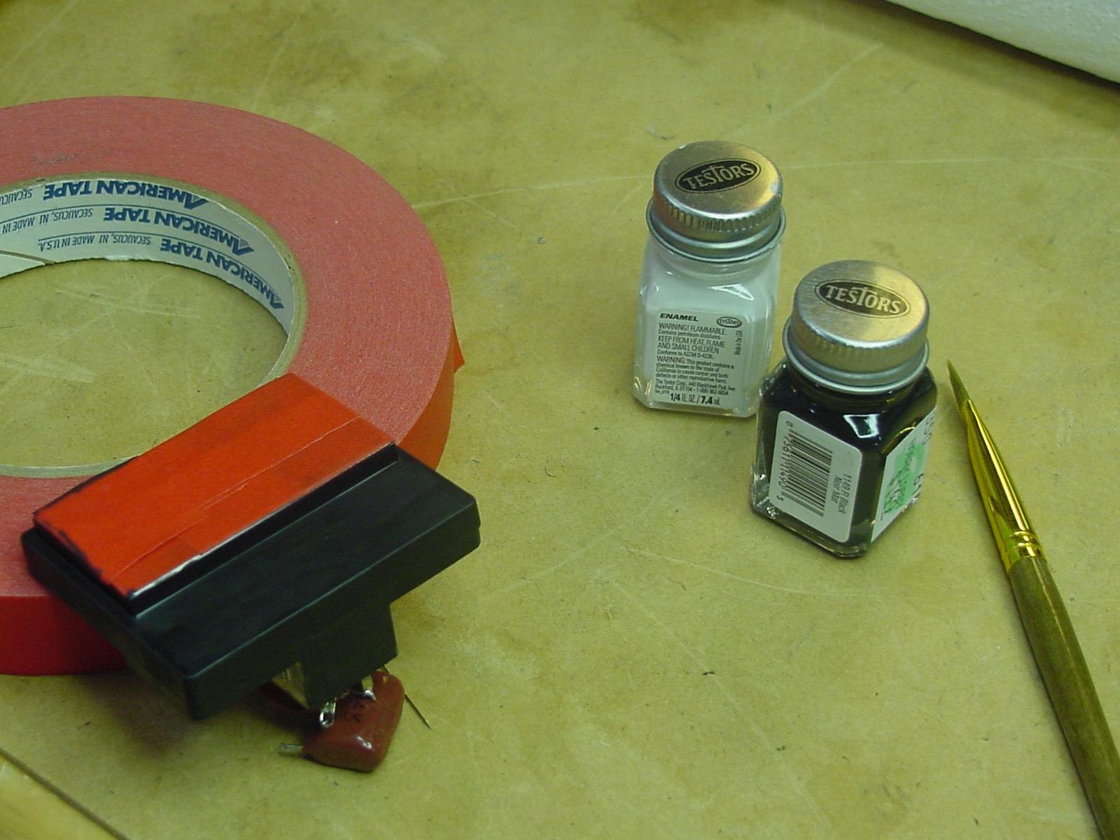 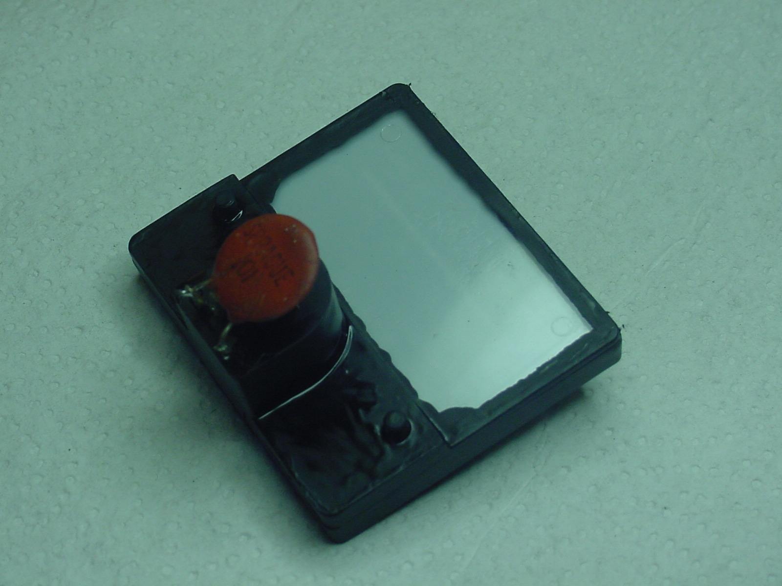 Painting the Meter Case - Front (L) and Back (R) I used painter masking tape to protect the scale area on the front of the meter during painting. Painting the back side is not as critical as long as you don't paint over any of the area where the scale will be back lit. Once the case paint has dried the masking tape is removed and your ready to go. Step 5: Testing and
Install
At this point I tested the meter on the bench. The TR7 meter is a
200uA meter. That does not appear in any of the Drake manuals
by-the-way. Here is a picture of the completed meter under test
at 100uA of current.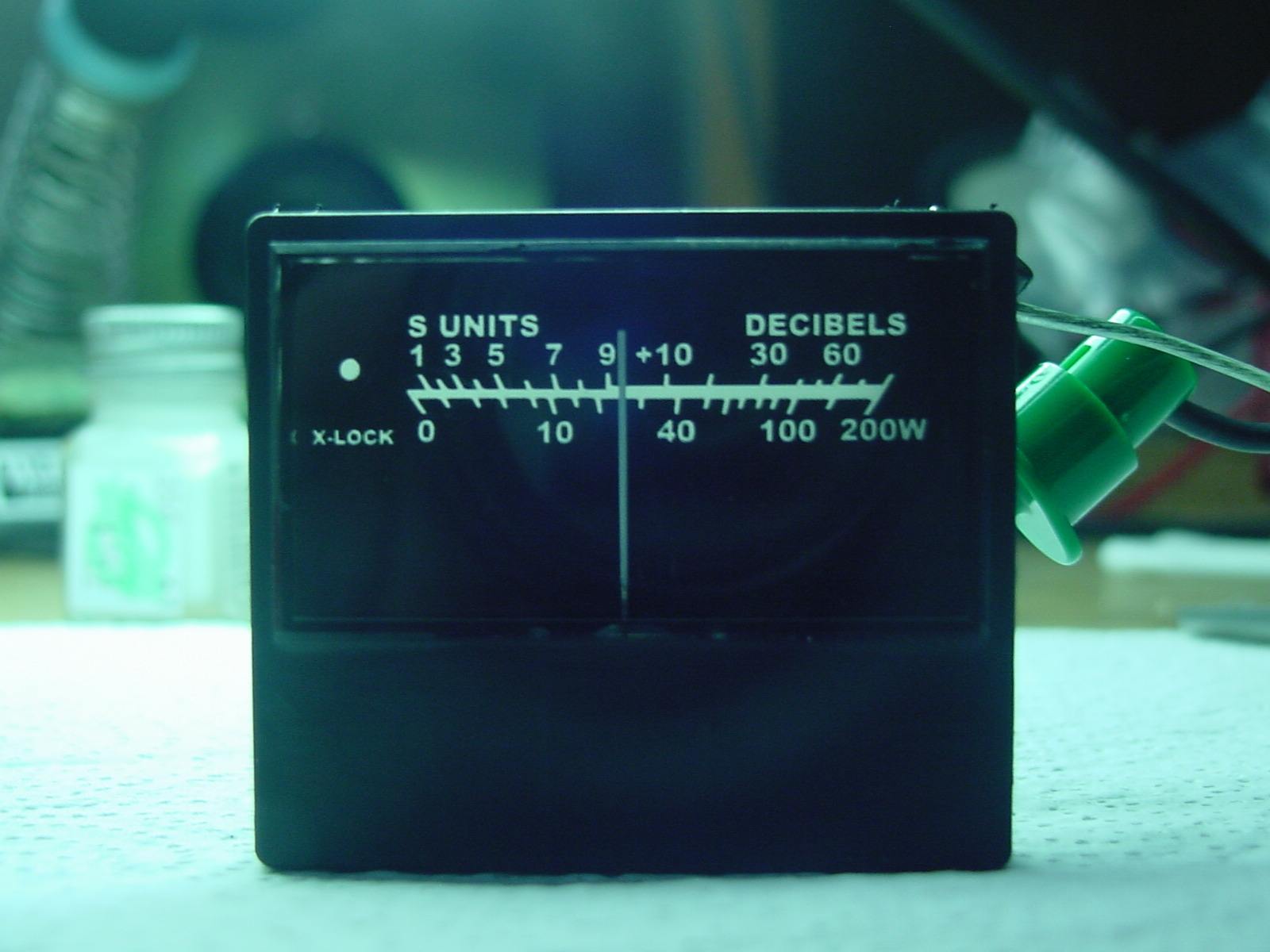 Completed Meter under 100uA Test Notice that the newly white
painted pointer needle is clearly visible in normal room light with a
black faced meter. Even on the work bench the meter scale and
labels appear white simply from the back side illumination of my shop
lights. Reversing our steps for the
removal of the meter it is now time to put things back in place.
Step 6: X-Lock LED
Placement
First lets have a look at the
completed meter installed and the X-Lock LED placement.
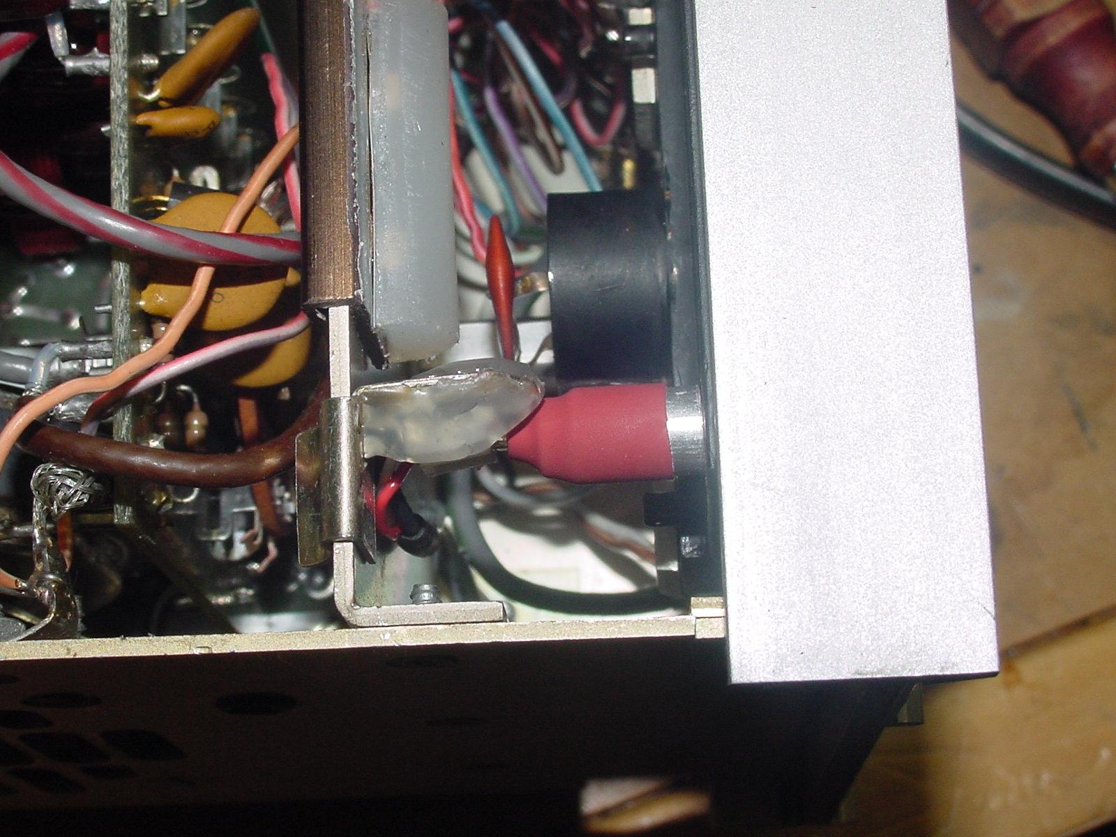 X-Lock LED Mounted Behind Meter The X-Lock Status LED is mounted
using an old clip from the original bayonet style lamp mount. The
bayonet portion was removed and a LED socket was attached in place of
the old bayonet socket using hot glue. I used a cable pulled from
an old computer to connect my LED to the X-Lock board. It uses a
three conductor cable with push-on connectors at each end. I
believe this cable was used for internal audio wiring from a CD
drive. The length was perfect for this project! The LED
leads plug into the connector. On the top of the LED I slid on a
small aluminum spacer, with an inside diameter that was a perfect fit
for the 5mm LED, and then covered that with heat shrink tubing
(red). The only light from the LED that is allowed to escape is
via the top of the LED through the center of the spacer. By using
the socket to hold the LED I was able to trim the LED leads so that
once the clip is slid onto the internal frame of the TR7 the edge of
the aluminum spacer (or should I call it a light tunnel) rests right
onto the back of the meter and right behind that little 3/32" dot I
added to my new scale. Using the clip mount and LED socket-ed
leads allows me to fine tune the LED placement so that it perfectly
lines up with the scale indicator dot.
Above the X-Lock LED is the blue back-light lamp for illuminating the rest of the meter scale and labeling. This lamp is my original LED back-light from the old meter. A Little Bit on my
X-Lock Installation
My installation follows that
presented by Marinos, SV9DRU and mentioned earlier in this
article. The following is the underside mounting of my X-Lock.
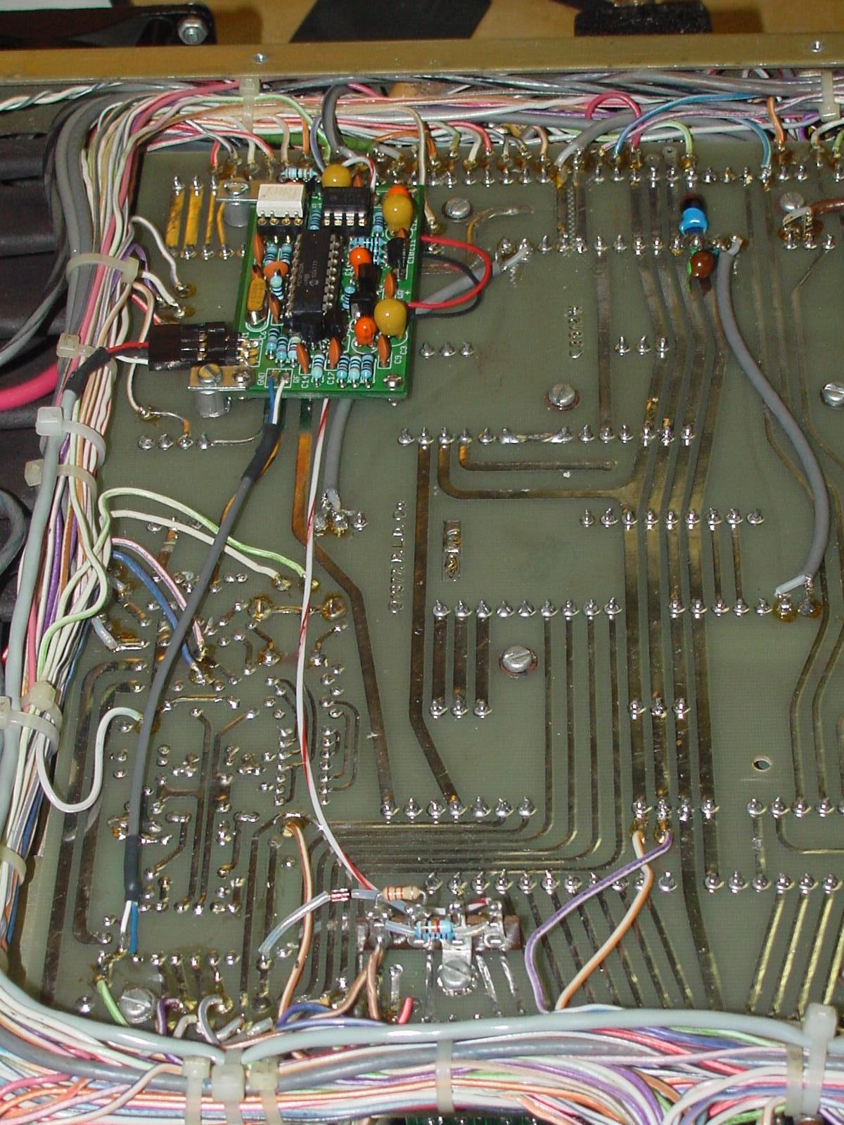 My X-Lock TR7 Installation Some things I've done differently.
1) On the lower portion of the picture I mounted all the RIT interface components on a small four contact terminal strip. There is actually a fair amount of head room for the X-Lock circuit. The bottom cover extends 1/4" beyond the frame rails that surround the Parent PC board. So you have around 3/4" to play with above that board. 2) As others have experienced the supplied header sockets and plugs can not be used as supplied. They will extend to high to allow placement of the X-Lock onto the Parent PC board. Ron, WD8SBB had a very good idea and he bent those headers 90 degrees to allow using them in his installation. However, I didn't find a need to make it plug-in-play so I soldered the RF (PTO IN), VAR and Power connections directly to the X-Lock board. 3) The LED output is the only connection that uses a header socket/plug connections. As I mentioned earlier the cable I used came from an old PC computer. The header on the X-Lock is a simple three pin 90 degree bent device. It's not keyed, but that doesn't matter since if the header plug is flipped upside down it will not harm the LED's or the X-Lock. 4) Also recommended by WD8SBB's document is the use of Tantalum Electrolytic capacitors in place of the provide electrolytics. The 100uFd Tantalums are about 3/16" shorter than the originals and thus do not have the potential of hitting the bottom cover of the radio. Also, using the Tantalums allows me to mount the X-Lock a little higher off the Parent board. I didn't have any 10uFd Tantalums, so I used 22uFd's in their place. 5) Similar to the SV9DRU mounting I used two original 4-40 mountings that hold down the Parent board. My mount brackets are more rugged than the re-engineered wire terminals that Marinos used. I pressed down on the X-Lock board with only the two small brackets supporting it and it would not bend down easily. However, as a safety measure I did place two screws with locking nuts on the non-bracketed corners using screws that are long enough to contact the Parent board. Thus the X-Lock board can not be pressed down closer and come in contact with the Parent. With my placement those support screw posts are not near any traces on the Parent board either. 6) If you place your X-Lock in the position shown here, there is a 13.6VDC (PCB Connection 11/30) and Ground (PCB Connection 11/28) available on the 2nd IF/Audio board solder pads on the Parent board. These connections are right next to the X-Lock board so there is no need to run long wires over to other parts of the radio. Final
The X-Lock worked fine right off the bat. I have been playing with it for several hours now and even with the default 2 second Post Tuning Delay (PTD) it has been working flawlessly. I've read of others changing their PTD's to as much as 10 seconds, but even with a great deal of fine tuning testing it unlocks and locks just as I'd expect it to. Thankfully it's easy to change the PTD on the X-Lock if I do discover that 2 seconds is to short in the long run, for now it's fine as delivered. I'm really pleased with the results of my meter modification and rebuild. The back lit meter scale with the X-Lock indication built-in sure makes it look and feel like this was the way Drake made it back in the early 1980's. Although my TR7 was never a drifty radio, having the X-lock allows for it's use with communications protocols that require additional stability that even the original stable PTO could not deliver. On to the next project - Don N9OO, July 26, 2011 |