| Collins 30L-1 Linear Amplifier
Restoration & Repair |
January 2008 A few years ago I bought a 30L-1 at what I felt was a fair price. Considering I knew it was in need of work! It attracted me because it was a later Round Emblem (RE) unit which ment it should have had all the Collins Service Bulletin changes installed. The seller also provide a extra set of tubes. The Obvious Needs - Cabinet and Trim Ring were in bad shape and needed repainting or replacement. - 120VAC power cord was in bad shape. The Obvious Good Things - It was a late production S/N 41188 MCN 4387 - All Service Bulletins should have been factory completed. - It was only about half the price of other nice 30L-1 amplifiers. About one year before I began the restoration I had found and purchased a almost new looking 30L-1 cabinet (no trim ring) so getting the old one repainted was thus no longer a priority. I had a repainted metal trim ring that was purchased a few years back for another project so I felt I had the outside cosmetics taken care of. I proceeded to open things up and begin the evaluation. Evaluation Results:
AC Power Switch
Thankfully the AC Power switch
resistance dropped down after an extensive workout of toggling and
rocking the switch on/off and back-en-forth! After a few
minutes both poles were measuring 1.3-1.5 ohms consistantly. The
resistance measurement is the switch in series with one of the 120VAC
primary windings. Thus the value slightly over one ohm is
normal. I just hope the reistance was a result of many years
of nonuse. Replacing these switches can be a real pain!
Fix
RF Connectors
I wanted to return the RF connections to the original Collins design. I needed to relocate the RF IN back to the RCA jack on the left back side of the transmitter. This ment removing the SO-239 now occupying the original ground connection and running a new piece of RG-58 coax to the original RCA. The SO-239 location was closer to the antenna relay so that piece of coax was to short to reuse. Getting a new piece of coax installed was a bit of work and required removing the relay retaining screws and a grounding strip near the relay. Both were then pulled away from the chassis to allow removing the old coax and installing the new. IMPORTANT NOTE: In this later 30L-1 Collins got away from the nice string lacing of cable bundles. Instead now they were using simple plastic cable ties. I do love the look of the string lacing better than the cable ties, but it sure is a great deal easier to remove wires or reroute wires held in the cable bundles by plastic cable ties. Cables ties can easily be cut and replaced with new ones after the wires have been replaced and/or rerouted. I wanted to return the original ground connection to the location of the replacement SO-239. So I made a small flange out of steel that was the same size as the flange on an SO-239. It is now mounted on the inside of the rear cover plate. A small hole was drilled for a grounding screw. To improve the look I added a thick aluminum washer (spacer) on the grounding post. This washer fills the hole from the old SO-239 connector. I countersunk the flange mounting holes and used flat head screws. I think it looks a little bit more professional. 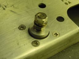 Original Ground returned in place of the modified RF IN Next
was the much easier return of the N-Connector in place of the SO-239
used in the RF OUT. On the back of that bracket is also the 39
ohm antenna relay resistor. I replace the original 1/2W carbon
comp resistor with a newer 1W NTE Flame Proof resistor. I
like
the NTE flame proof resistors as the 1W size is pretty much the same as
the old 1/2W carbon comp resistors.
Grid
Resistor Replacement
The 811A grid resistor that
measured 91 ohms instead of 47 ohms physically looked fine. After
being unsoldered it just snapped in half! So obviously
outside
appearance doesn't mean squat! Since I'm in replacing one
resistor I decided to do them all. Again using NTE flame proof
resistors. This time I stayed with the original 1W rating, even
though the new ones are pjhysically smaller than the originals. I
added Teflon tubing to all the resistor leads.
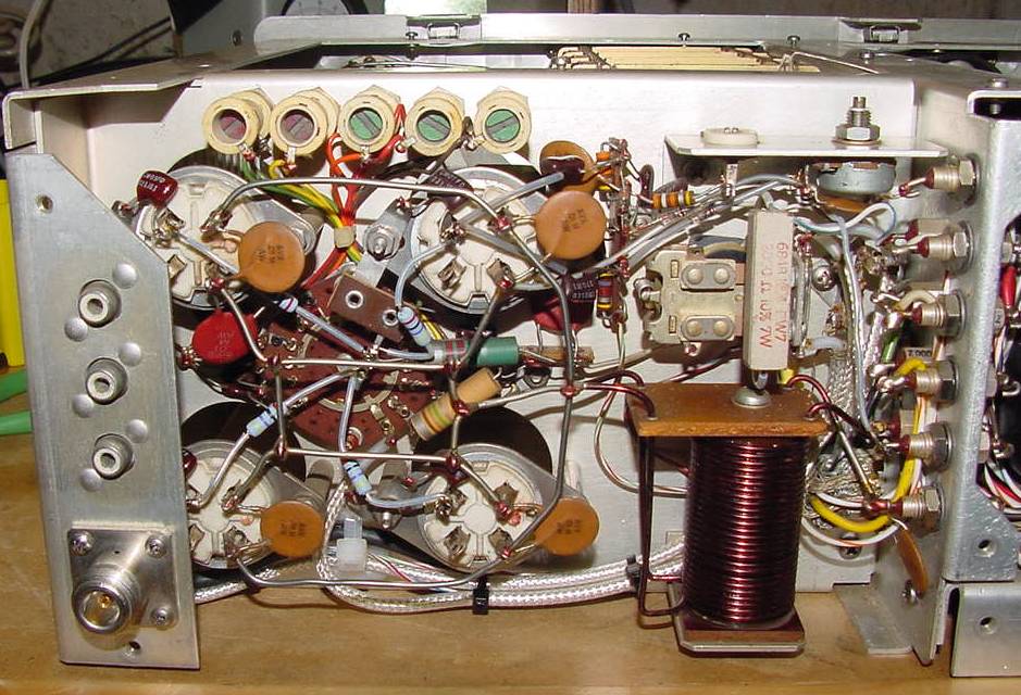 New RF OUT N-Connector on left side and new grid resistors with common connection point near the center of the tube sockets HV
Work
Instead of replacing all the HV
board diodes and electrolytic capacitors, plus checking out all the
equalizing , bleeder and dropping resistors I opted for one of the
replacement boards. In my case it was the Bill Noonan, W6BN circuit board.
The reason was simply it was a professional grade single
board
replacement. The original Collins diode and cap/res boards are
both replaced. In their place is one PCB mounted above the
chassis.
Installation is quick and painless. Taking my time it only took a
little over an hour. Remember though I already had the amplifier
opened up for my other work.
 The W6BN HV Board offer a clean replacement solution AC Input I want to operate my 30L-1 from
240VAC which I have available in the shack. If there is one
shortcoming to the 30L-1 amplfier it is that Collins did not make
conversion from 120VAC to 240VAC and vise vera an easy affair. I
guess I'm used to modern equipment that normally will have simple screw
terminal jumper changes for such a voltage input change. Even
though the schematic has a marked terminal block drawn with the numbers
1
through 5, in reality it is just s simple solder terminal strip.
Such an arrangement is a call to disaster if the unit gets switched
back-and-forth enough times. A look through my junk box and I
found a neat screw terminal block replacement . Interestingly it
was
actually engraved with the numbers 1 through 5 just like the Collins
schematic. As you can
see all the AC input wires from the line cord now connect via push-on
terminals. Changing to 120VAC in the future will be a simple
movement of the line cord terminals and the movement of one or two
terminal-to-terminal jumpers. All original transformer primary
winding connections, jumpers and bypass noise capacitors use simple
eyelet terminals that now screw down for ease of removal and/or
relocation.
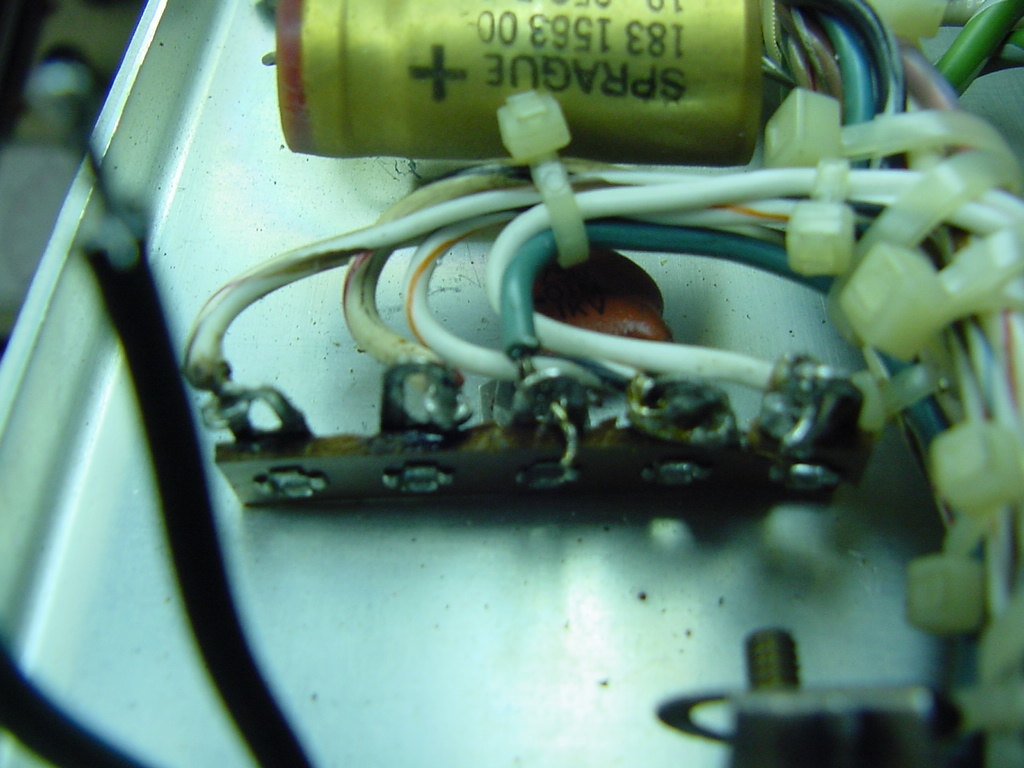 Collins Original AC Input Terminal Strip (AC Line Cord already removed) 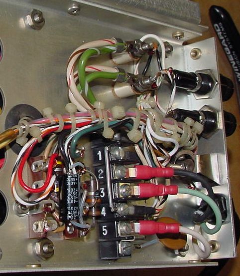 My Replacement AC Input Strip - The Way Collins should have done it! Just to the left of the new AC
Input Strip above is the LV DC power supply circuit. There is a
10uF 250VDC electrolytic capacitor that should also get replaced
here. Note this picture shows the new cap in place.
Also, notice the small wire (#30) that runs between the two lower terminals of that terminal strip at the far left. That is actually a fuse in the center tap to ground of the filament voltage secondary. If you have a 30L-1 that is experiencing hum in the output signal this little fuse wire may be blown. The tube filament will still glow when this wire is blown! Beware.. Check Out
Before buttoning it all back up I
did go through and check all remaining components, except those on the
new HV
power supply board. Everything else checked out. I
originally applied 24VAC to the line cord to verify that all the HV and
LV DC voltages came in at 1/10th the expected value once 240VAC
was finally applied. It's much safer working with a HV of 200VDC
than 2000VDC! You will need to slide a little bit of
insulation tubing over the three interlock switch shorting posts to
prevent shorting out the DC voltage. The HV and LV voltages
checked out fine at 1/10th their normal operating values. Do not forget to
remove the tubing before you button up the internal covers!
Installed the four 811A tubes and screwed all internal cabinet
covers back in place.
Tuning
With the amplifier connected to the 32S3A I retuned all the input circuits per the proceedure in the Collins manual. I did not perform the Tune Meter or ALC Threshold adjustments. I figured if I noticed that there was a problem relating to these areas in use I could always come back and perform those adjustments. On my 30L-1 there are adjustment holes in the top of the RF cage to access those adjustment points. So it would not require case removal in the future if such adjustment is needed. Trim Rings
I knew that the Collins KWM-2A used a slightly different trim ring from the others as it has additional holes under the cover edge for locking type screws. I had a very nice repainted metal trim ring for use when I finished this 30L-1. However, when I tried attaching it I ran into a problem. Collins would add additional metal to the rear side of trim ring to add strength. On the 30L-1 just like the 75S3 or 32S3 units they have flat head screws located about 3.75" each side of front center just under the top cover lid. The ring I had did have these holes, but underneath this particular trim ring some of that reinforcement came to close to those holes. If you go back to the picture of the HV section and look at the top right side you can see the L-brackets on the 30L-1 with mounted retaining nuts attached. Well those L-brackets would not clear the reinforcement metal added to my trim ring! The orginal trim ring I had on this 30L-1 was plastic and it was cracked in half. However, I did have a couple of others that are in need of getting sand blasted and repainted. So for now I am using one of those metal trim rings. I don't think they were from a 30L-1. So I'm not to sure why the differences. For now I'll use the scratched up trim ring until I can visit a local powder coating business and see about getting a small collection of cabinets and trim rings I currently have repainted. I must say out of all my S-line equipment the 30L-1 trim ring was the hardest to install. Since the 30L-1 is essentially a full cabinet within a cabinet many of the inner cabinet mounting screws will easily hit the trim ring while it is slid on. When I do get a nicely painted trim ring I will be extra careful and SLOW installing it to avoid nicks! I put on the scratched up metal trim ring and the like new cabinet. Moved it into the shack for the trial run. I have made a few one hour plus QSO with the 30L-1 driven by my 32S-3A transmitter. It has performed flawlessly! I get about 600 watts output on the 312B4 meter on 75 meter phone. Fan
Balancing
After I had everything back together I did notice the fan was making a little vibration noise. The Collins manual does indicate the fan should be lubed every six months. Yeah right! I did lube it while I had everything open and I knew the fan turned smoothly by hand. Bad bearings were not suspect. Since my fan blades were kinda dirty I did clean them up during the refurbishment. I noticed how easy it was to bend them as they are a light aluminum. Perhaps it was wobbling due to one of the blades being off as a reult of cleaning them.. Opening the final cage cover and slowly rotating the blades by hand, I could use the air openings along the bottom of the cage as a reference point to watch the edge of each blade as it turned. They weren't off by much, but I did do a little treaking so that visually they all lined up against my reference point. Buttoned it all back up and applied power. No more noise! Before I forget. I did mention the amplifier came with a extra set of tubes. I had always figured they were new or good replacements. The installed tubes were all RCA JAN versions. The backup set was four Cetron versions. After looking over the Cetrons I came to the conclusion that I bet they were previous pulls from this amplifier. One of the tubes had a slight caving in of the plate near the top of the tube. So much for an extra set. Lesson learned - "Extra Set" does NOT mean new or even working set! I do think a couple of them may be fine, but I'll need to make a test fixture to verify that.  The completed 30L-1 RE. If you look closely you can see the scratches in the trim ring |