Transceiver
|
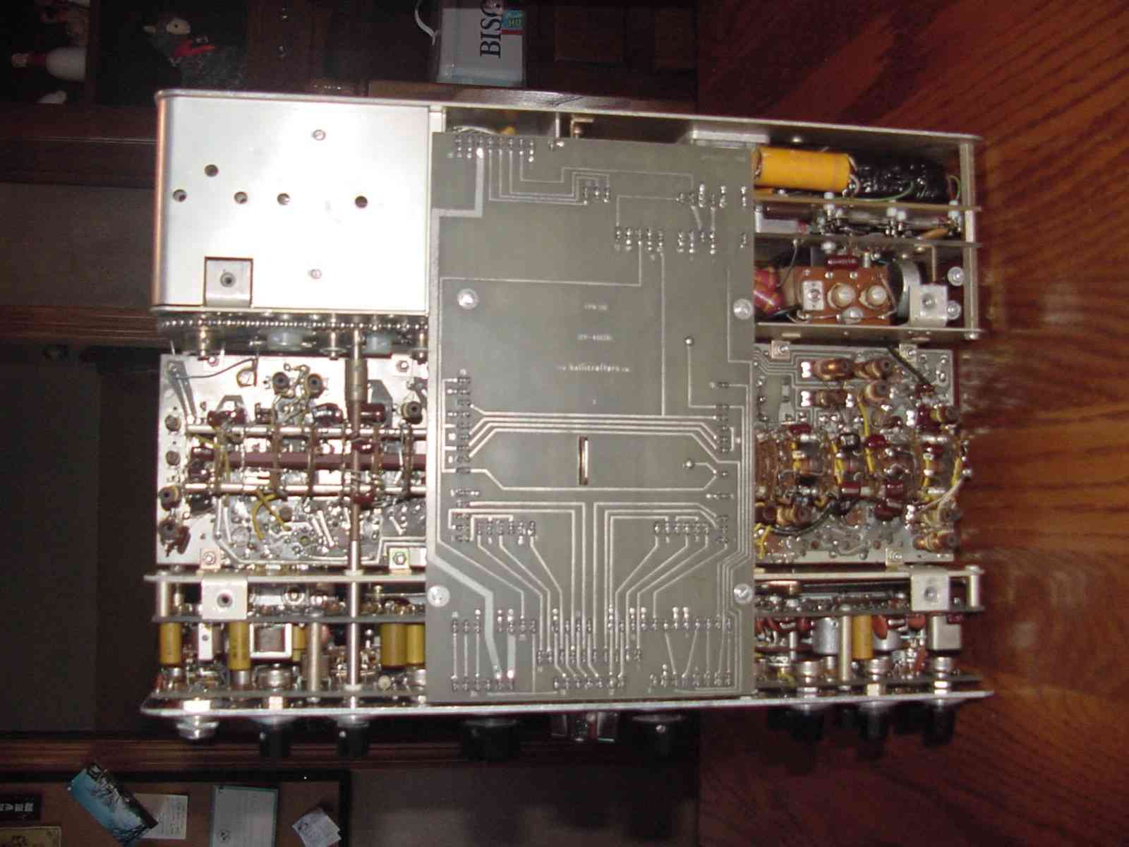
On the previous views of the rigs underside the large PCB in the center
was removed to show specific modules. However, when a working rig is first
opened this is what you would see, albeit with a large protective cardboard
cover over the PCB assembly. That large PCB is used to electrically connect
all the sections of the radio together. Using spade and clip terminals
this board provides a reliable method for getting everything talking. One
of the first things you will notice on the FPM-200 is that there is no
wiring harness! With the exception of the circuitry around the band switches
most all other components are PCB mounted. Boy are they! The PCB material
is top notch. All boards are glass-epoxy material and 1/8th inch think.
As I mentioned before all PCB's are tin plated and in this particular FPM-200
very little oxidation has occurred over the years. Behind the front panel are two vertically mounted PCB's. One directly behind the front panel which is used to mount all the front panel controls and some of their associated circuitry. Another vertical PCB is located about two inches back. This also contains a great deal of the transceivers circuitry. |