Transceiver
|
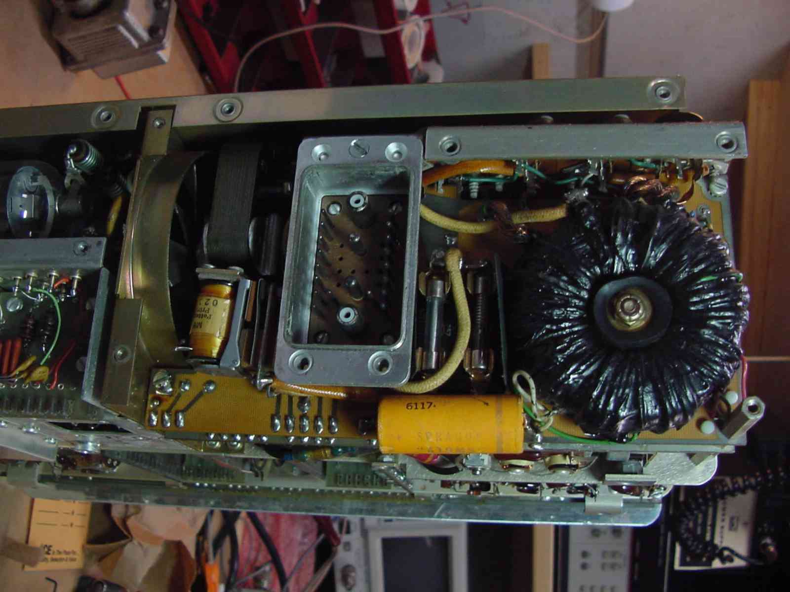
Removing the back panel reveals the DC-DC Converter. The FPM-200 is designed
to operate from 12VDC like many of our current day rigs. Therefore mobile
operation is designed in. Since the transceiver does use tubes in the final
amplifier and driver stage a high voltage DC source is needed. A 1400cps
square-wave oscillator, utalizing four large power transistors, can be
seen in the fully open top view of the rig. The large black toroid in the
picture is a transformer that steps up the square-wave voltage to a high
voltage. This in turn is rectified by diodes and filtered to produce 800
VDC for the 6146 plates. Also produced is a 270 VDC low voltage for driver
tube and screen grids and a negative bias supply voltage. In the center of the picture is a military style Cannon multipin connector which is the only connector on the rear of the radio! This connector carries all the RF, DC, Audio and control signals needed for operation. On the left next to the relay is a small AC fan that is used to cool the RF Amplifier unit. Yes, I said AC. The shaded-pole fan motor is a 60 cycle type which also is driven by a square-wave oscillator consisting of two more of those big power transistors. Just to the right of the Cannon connector are two glass fuses. There is a small cover plate on the rear which can be removed to access the fuses only. Therefore, the entire back cover does not require removal just to change a fuse. |